



Reading steel structural drawings starts with one habit: follow the mark. Every beam, column, and brace on the sheet carries a unique label. Once you can trace that label from the framing plan to its section detail to the bill of materials, the rest of the set falls into place. A full package looks dense, but it runs on a small, repeatable vocabulary — grid lines, member marks, shape callouts like W12×26, and a short set of weld and bolt symbols. The sections below walk that vocabulary in the order a fabricator reads it, so you can open a set and see what gets built, where each piece goes, and how it all connects. This guide covers interpreting an existing set, not sizing members or writing weld procedures, which stay with the engineer of record.
What steel structural drawings are — and the three sets you’ll receive
Structural steel drawings are the coordinated package of plans that tell a fabricator and an erector exactly which members to make and where to place them. People often say “the blueprint” as if a job has one drawing, but a steel project usually arrives as three different sets, each prepared by a different party for a different job. Confusing them is the first mistake new readers make, because a dimension that is reliable on one set should never be scaled off another.
The first set is the design, or structural, drawings, prepared by the engineer of record. These carry member sizes, the grid, design loads, and the general notes that fix steel grades, bolt types, and weld requirements for the whole project. They are the output of the steel building design stage and describe intent, not piece-level fabrication.
The second set is the shop, or fabrication, drawings, prepared by the steel detailer or fabricator from those design drawings. A shop drawing shows one member at a time with every cut, hole, cope, and weld dimensioned, so the shop can build that exact piece. The third set is the erection drawings, also called general arrangement (GA) or marking plans, which show where each finished, marked piece sits in the assembled frame. Together they turn a steel frame construction project into something a crew can both fabricate and assemble.
| Drawing set | Prepared by | What it shows | When you use it |
|---|---|---|---|
| Design (structural) drawings | Engineer of record | Member sizes, grid, design loads, general notes | Understanding design intent and specifications |
| Shop (fabrication) drawings | Detailer / fabricator | Every cut, hole, cope, and weld for each piece | Fabricating each individual member |
| Erection (GA / marking) drawings | Detailer / fabricator | Where each marked piece sits in the frame | Assembling the frame on site |
Where to start: the title block, sheet index, and scale
Every sheet opens with a title block, and reading it first keeps you from misreading everything after it. The block carries the sheet number, sheet title, project name, revision number and date, the scale, and who is responsible for the drawing. The revision number matters most in practice: a cloud or a triangle flags what changed, and building from a superseded sheet is a classic source of rework.
Steel sheets sit inside a larger set with discipline prefixes — S for structural, A for architectural, M, E, and P for the trades — and they run in a logical order. Open the cover and sheet index, read the general notes, then move from the overall framing plans to the sections and details they reference. Treating the full set of metal building plans as one cross-referenced document, rather than loose sheets, keeps members, elevations, and connections aligned.
Scale tells you how a drawn length relates to the real one, shown as a ratio such as 1:100 or 1:50, or in imperial form like 1/4″ = 1′-0″. GA plans are usually drawn at 1:100 or larger so every erection mark is legible. One rule overrides the scale, though: build to the written dimensions, never to a length measured off the sheet, because printing and PDF scaling distort the geometry while the figures stay true.
Locating every member: grid lines, elevations, and member marks
Grid lines give every member an address: letters run one way, numbers run the other, and each column lands at a lettered-and-numbered intersection. A column called out at C-3 sits where grid line C crosses grid line 3, and beams are described by the two gridlines they span between. This coordinate system lets the design, shop, and erection sets all point to the same location without ambiguity.
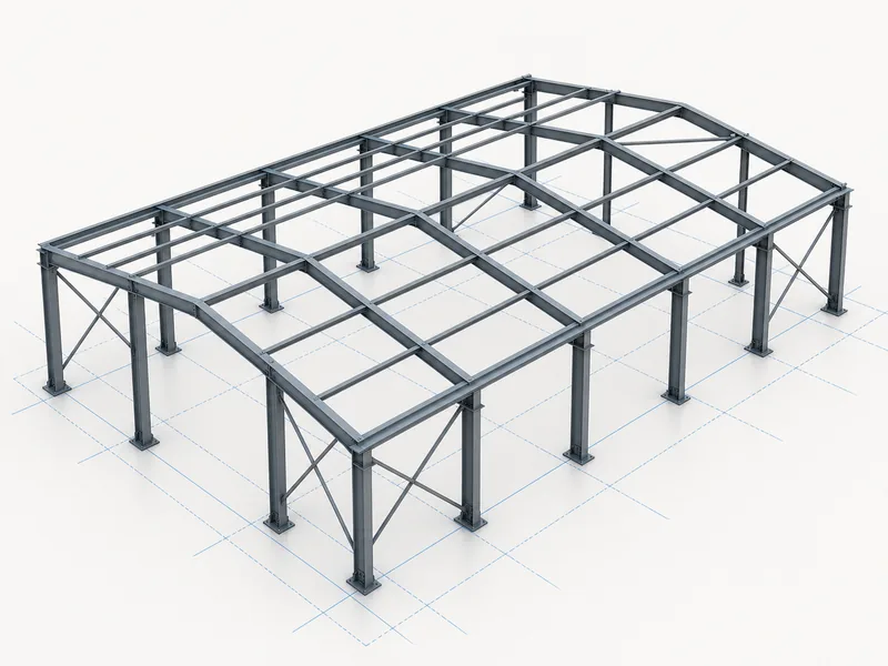
Grids fix horizontal position, and elevations fix height. Drawings note levels against a project datum — top of steel (TOS) and bottom of steel (BOS) are the two you will read most — using values like +12′-0″ or EL 100.00. Read alongside the grid, an elevation places a member in three dimensions instead of two, which matters when beams frame in at different heights within the same bay.
Each piece then gets a member mark, or piece mark — a short label such as C1 for a column type or B5 for a beam. Identical pieces share one mark, so the shop builds and ships them as a batch. The mark is the thread of the whole set, tying the framing plan to the shop drawing and to the bill of materials. Secondary members carry their own marks too, so a purlin or a girt will appear as something like P1 or G1 on the roof and wall framing plans. The GA also tells you the frame type at a glance, whether you are reading a rigid frame or a trussed bay, and our portal frame vs truss comparison covers when each is used.
Decoding the drawing’s vocabulary: shapes, welds, and bolts
Steel drawings lean on a compact symbol set, and four families cover most of what you will meet: shape designations, weld symbols, bolt callouts, and section markers. Learn these four and the dense-looking notation becomes readable.
Shape designations
A shape callout names the member’s profile and size in a fixed pattern. In the AISC system used on US drawings, W12×26 is a wide-flange member about 12 inches in nominal depth weighing 26 pounds per foot. The letter is the shape family, the first number the nominal depth, the second the weight per foot. The wide-flange shapes that carry most frames are what people loosely call I-beams; our guide to the i-beam building covers where they fit. European drawings use a different convention, such as UB 254×146×31 in millimetres and kilograms per metre.
| Callout (example) | Member type | How to read it |
|---|---|---|
| W12×26 | Wide-flange beam/column | ~12 in nominal depth, 26 lb/ft |
| HSS6×6×1/4 | Hollow structural section | 6×6 in, 1/4 in wall |
| C10×15.3 | Channel | 10 in deep, 15.3 lb/ft |
| L4×4×1/4 | Angle | 4×4 in legs, 1/4 in thick |
| WT6×20 | Structural tee | cut from a W-shape, ~6 in, 20 lb/ft |
| PL1/2×8 | Plate | 1/2 in thick, 8 in wide |
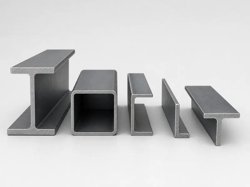
The general notes name the steel grades behind these shapes — commonly A992 for wide-flange, A500 for HSS, and A36 for plate and angles — so you rarely need them repeated at every member.
Weld symbols
Weld symbols follow the AWS A2.4 convention: a horizontal reference line, an arrow pointing to the joint, and the weld type set above or below the line. The symbol shape gives the weld type (a triangle for a fillet, for instance), the size sits to the left, and the length to the right. Two add-ons carry a lot of meaning. A flag at the bend means a field weld, made on site rather than in the shop. A small circle at the same point means the weld runs all the way around the joint, and a tail on the reference line holds a note such as the welding process or electrode.
Bolt callouts
Bolt notation states the grade, diameter, hole type, and count. High-strength structural bolts are called out as A325 or A490, now grouped under ASTM F3125, with a diameter such as 3/4″. The hole type — standard, oversized, or slotted — affects how much the connection can be adjusted in the field, and slotted holes in particular signal where movement is expected.
Section and detail callouts
A section or detail callout is a circle split with a number over a sheet number, paired with a cut line showing the viewing direction. The top number is the detail, the bottom is the sheet it lives on, so a callout reading 3 over S-501 sends you to detail 3 on sheet S-501. Following these references opens a flat framing plan into the connection it depends on.
From plan to piece: connections, schedules, and the bill of materials
Connection details and schedules are where a drawing set turns from a picture of the frame into a parts list you can fabricate and check. The connection details show how members meet: a shear tab or end plate at a beam, a base plate and anchor bolts at a column, or a gusset plate at a brace. They also note whether each joint is bolted, welded, or both, and the section callouts on the framing plan route you to them.
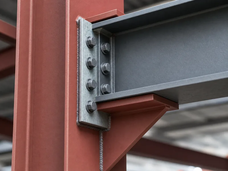
Schedules and the bill of materials make the set countable. A column schedule or beam schedule lists members by mark, size, length, and end condition in tabular form, which lets an estimator count tonnage quickly. The bill of materials, tied to the marking plan, binds every mark to a quantity and a weight, and that controls both fabrication and shipping.
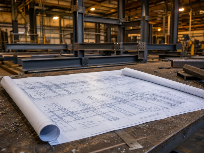
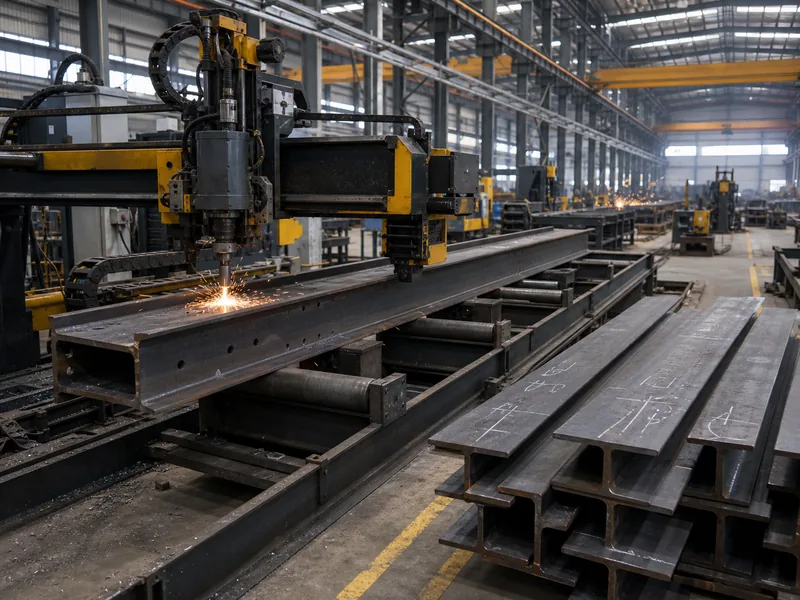
This is where a mark becomes a physical piece on the shop floor. At our plant, a mark on the marking plan pulls the matching shop drawing. The profile is cut on the dedicated H-beam, box-section, C/Z purlin, or steel-plate line, and holes and copes follow the fabrication detail. The finished piece is then stamped with that same mark before it ships under ISO 9001 quality control. The reason that traceability matters is plain: the erector who finds B12 on the plan has to find B12 on the steel, or the frame does not go together. Every line on a framing plan is a real metal building component that has to be cut, marked, and delivered to match.
A few reading mistakes show up again and again:
- Scaling a dimension off the sheet instead of reading the written figure.
- Building from a sheet that a revision cloud has superseded.
- Reading a member mark as if it were the shape size.
- Skipping the general notes, which set the bolt grade, weld electrode, and finish for the whole job.
Catching these is mostly discipline, not skill. When a load note, connection, or revision reads as ambiguous, confirm it with the engineer of record before any steel is cut. Reading a set well also means knowing which calls are not yours to make.
Conclusion
A steel drawing set rewards a fixed reading order more than raw memorization. Open the title block and general notes, walk the grid to place each column, follow every member mark from the framing plan to its section detail, then confirm the shape callout and connection against the schedule and bill of materials. The single cross-check that saves the most rework is also the simplest: the mark on the plan, the mark on the shop drawing, and the mark on the fabricated piece all have to agree. The dimensions you build to are the written ones, too — never a length scaled off the sheet. Line up those marks and notes before any steel is cut, and a dense set of drawings becomes a frame you can actually build.
FAQ
What is the difference between shop drawings and erection drawings?
Shop drawings detail how to fabricate each individual piece, while erection drawings show where those finished pieces go in the assembled frame. A shop drawing gives every cut, hole, and weld for one member; an erection or marking plan gives the member’s mark and its position on the grid. Fabricators work mainly from the shop set, and erection crews work from the marking plan.
What does W12×26 mean on a steel drawing?
W12×26 is a wide-flange member roughly 12 inches in nominal depth that weighs 26 pounds per foot. The W is the wide-flange shape family in the AISC naming system, the first number is the nominal depth in inches, and the second is the weight per foot. Nominal depth is a label rather than an exact measured height, and European drawings use a metric convention instead, such as UB 254×146×31.
Who prepares structural steel drawings?
The engineer of record prepares the design drawings, and the steel detailer or fabricator prepares the shop and erection drawings from them. Design drawings carry the member sizes and general notes, and the detailer translates that intent into piece-level shop drawings and a marking plan. Knowing who authored a sheet tells you how much detail to expect and who to query about a discrepancy.
What does a flag on a weld symbol mean?
A flag at the bend of a weld symbol means the weld is made in the field, not in the shop. The rest of the symbol reads the same way — weld type above or below the reference line, size to the left, length to the right. The flag, though, tells the erector to make that joint on site, and a small circle at the same point means the weld runs all the way around the joint.
What are TOS and BOS on a drawing?
TOS marks the top of steel elevation and BOS marks the bottom of steel, both measured against the project datum. These elevations set how high each beam or column sits, independent of the plan position fixed by the grid. Read together with the grid, they locate a member in three dimensions rather than two.
Further Reading
- American Welding Society — welding codes and standards — Standards body. The AWS structural welding code and symbol standards, including AWS A2.4, define the weld symbols you decode on a drawing.
- OSHA — Steel Erection (Subpart R) — U.S. Department of Labor. Sets the steel erection rules and the erection-drawing requirements that govern how marked pieces are assembled on site.
- SteelConstruction.info — Steelwork specification — BCSA / SCI industry resource. Explains what general arrangement, fabrication, and marking drawings must contain as contract deliverables.