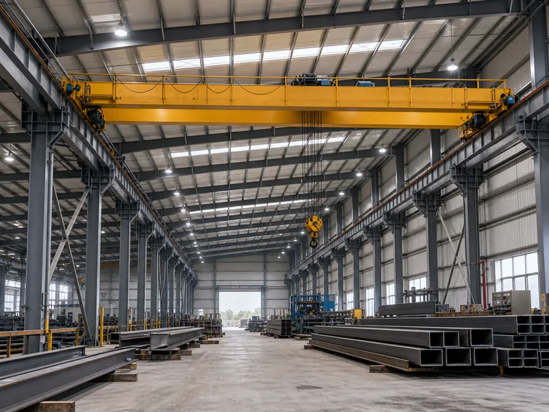
A crane beam is the runway girder that carries an overhead bridge or gantry crane along the length of a steel building, and it is engineered around moving, repeated loads rather than the static weight an ordinary floor or roof beam supports. In a workshop, factory, or warehouse, this member runs along each side of the crane bay, takes the wheel loads of the crane and whatever it lifts, and transfers them down through brackets into the building columns and foundation.
This guide covers what makes crane beam design different, the loads the beam must resist, how the crane’s service class shapes the design, how to choose a section, and the deflection and fatigue limits used to verify it. It does not cover selecting the crane itself, runway electrification, or foundation design; each of those is a separate task, and stretching this article to include them would only blur the part that matters: the beam.
Why a Crane Beam Is Not Just a Bigger Steel Beam
A crane beam carries dynamic, repeating loads, and that single fact reshapes every design decision that follows. A floor beam is sized mostly for static strength and a comfortable deflection limit. A crane beam sees the same wheel loads thousands of times over, takes a sideways shove each time the crane skews on its rails, and absorbs a vertical jolt when a load is hoisted. The controlling check therefore shifts away from pure bending strength toward serviceability and fatigue.
The repetition is the reason. When a crane cycles dozens or hundreds of times a shift, stress reversals build up at welds and connection details, and a beam that passes a single static strength check can still crack after years of service. Designers respond by tightening deflection limits, detailing connections to avoid stress concentrations, and checking fatigue explicitly for busier cranes, none of which a routine beam schedule would ever flag.
Loads a Crane Runway Beam Must Resist
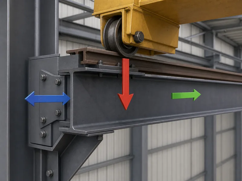
Crane runway beams resolve four distinct load actions, and missing any one of them is a common path to an undersized runway. The vertical wheel loads are obvious; the horizontal and longitudinal actions are the ones thin designs tend to underestimate. Each is normally expressed as a factor or percentage applied on top of the static wheel loads, with the final values set by the governing crane and structural standards, the crane supplier’s data, and the engineer of record. Commonly referenced guidance includes CMAA 70 and AISC Design Guide 7.
Vertical and impact loads
Vertical load is the wheel load of the crane plus the lifted load, increased by an impact factor that accounts for hoisting and travel. The impact allowance commonly falls in the range of about 10% to 25%, depending on how the crane is operated and which code applies; cab- and pendant-operated cranes usually carry the higher allowance, floor-operated ones the lower. The static wheel load alone is not enough to size the runway.
Lateral side-thrust loads
Lateral load is the side-to-side thrust generated as the trolley accelerates and the crane skews on its rails. It is commonly taken as roughly 10% to 20% of the combined weight of the lifted load and trolley, split between the two runways, with the exact percentage set by the governing crane design criteria, such as CMAA 70, and the crane data. Because this force acts on the top flange, it drives the lateral stiffness of the beam, not just its vertical capacity.
Longitudinal braking loads
Longitudinal load is the back-and-forth force created when the crane bridge starts and stops along the runway. It is usually estimated at about 10% of the wheel loads on the driven wheels and is carried into the longitudinal bracing and runway stops, not the beam’s bending. Leave it out and the bracing and end connections end up under-designed.
Fatigue from repeated cycles
Fatigue loading is the cumulative effect of all those cycles over the crane’s service life, and for busy cranes it governs the connection details. A runway under a heavily used crane can see several million stress cycles at its connections, so fatigue normally has to be checked for higher service classes. For standby or very light-duty runways it may not govern, but the engineer should confirm the criteria. Welded attachments, beam-end copes, and stiffener terminations are the usual crack-initiation sites.
Matching the Beam to Crane Service Class
The crane’s service class sets how strict the runway design has to be, so it is the first thing to pin down. Bridge cranes are graded by duty, from CMAA Class A standby cranes that lift only occasionally to Class F cranes in continuous, critical service. That grade decides both the deflection limit you design to and whether fatigue controls the connections. A Class B maintenance crane and a Class E foundry crane on the same span are not the same design problem.
As the class rises, the allowable deflection tightens and fatigue moves from a secondary check to a governing one. A light-duty runway can be designed to a relatively relaxed vertical deflection limit, while a severe-service runway is held far tighter and has every connection detailed for fatigue. Settling the class up front prevents the expensive rework of discovering, late in design, that the connections all need to be re-detailed.
Choosing a Crane Beam Section
The right section follows from span, crane weight, and service class rather than from any single rule of thumb. Shorter, lighter runways are often handled by a hot-rolled wide-flange (H-section) beam, which is the simplest and most economical to fabricate. As spans and wheel loads grow, fabricated sections (a welded plate girder, a built-up beam with a channel cap on the top flange, or a box girder) become more efficient because they put steel where the bending and lateral demands are. For long spans or heavy duty, a truss-type runway can be lighter still.
| Section type | Typical fit | Why it is chosen | Watch-outs |
|---|---|---|---|
| Hot-rolled H-section | Shorter spans, lighter cranes | Simplest and most economical; readily available | Limited top-flange lateral stiffness on longer spans |
| Welded H / plate girder | Medium spans, heavier wheel loads | Web and flanges sized to the demand | Welds introduce fatigue-sensitive details |
| H-section with channel cap | Where lateral thrust controls | Channel stiffens the top flange against side-thrust | Biaxial bending makes design iterative |
| Box girder | Long spans, heavy or high-class cranes | High torsional and lateral stiffness | Heavier and more fabrication-intensive |
| Truss runway | Very long spans | Lightest option for the span | More connections to detail and inspect |
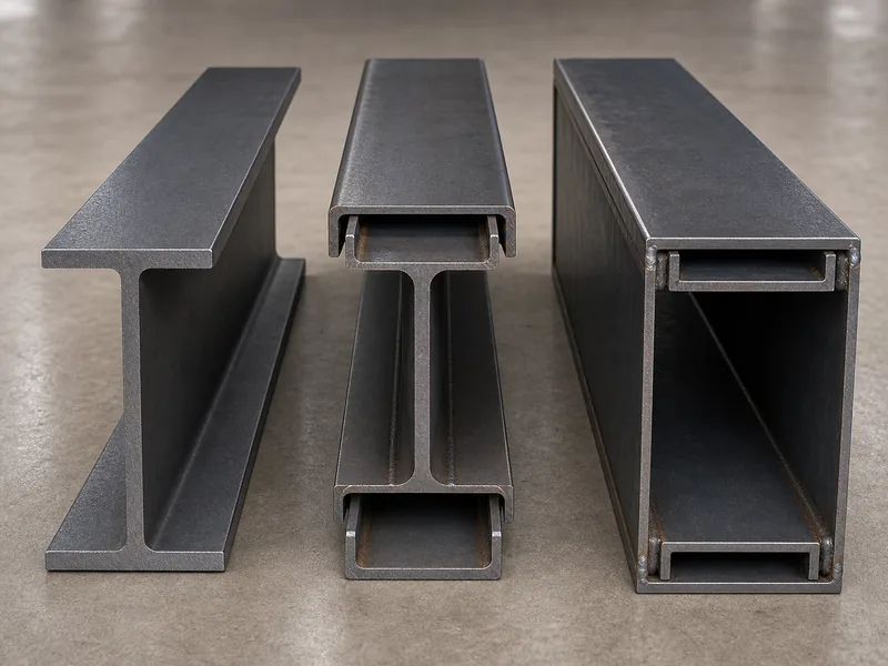
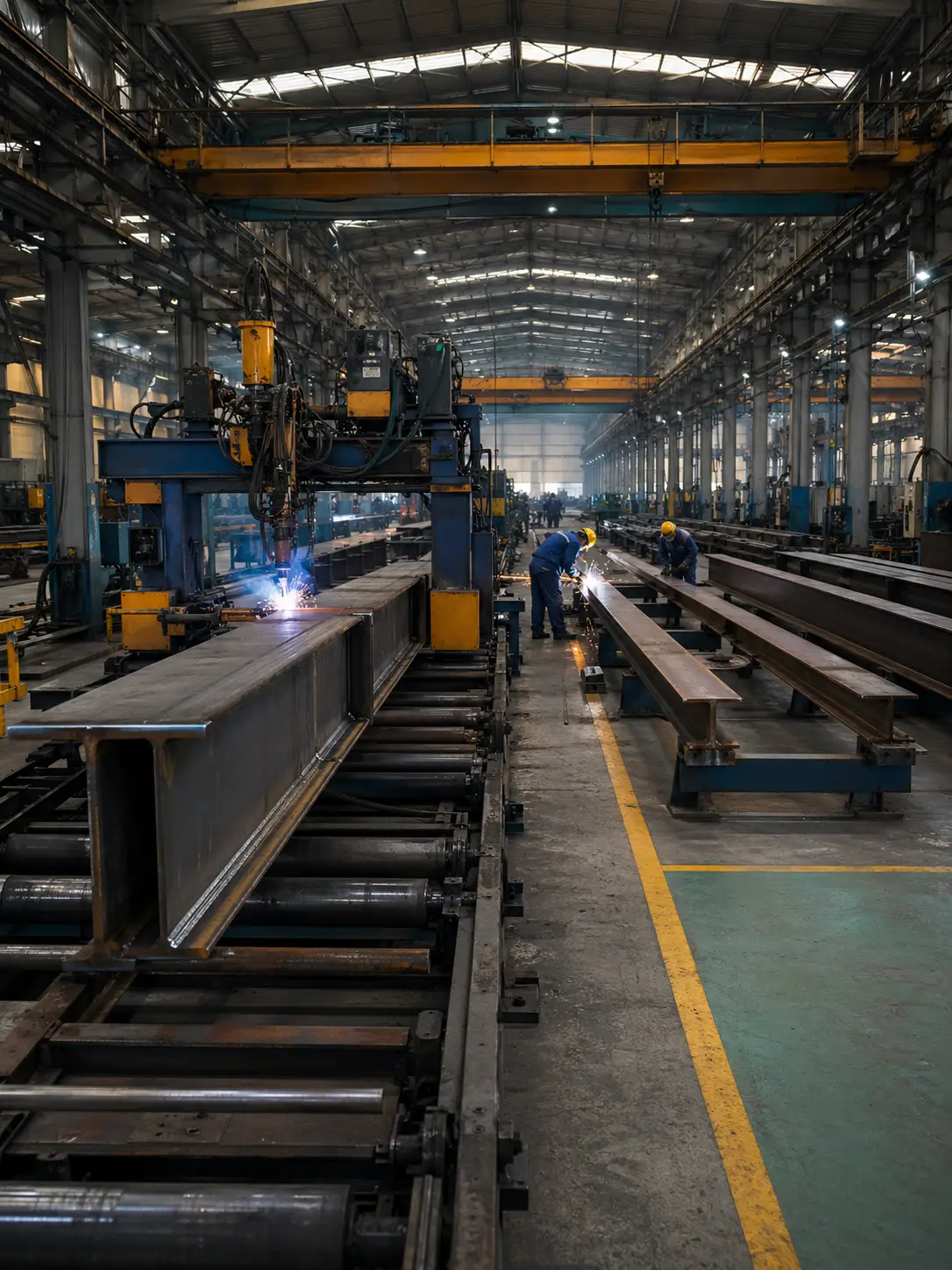
A channel cap on the top flange is one of the most useful details for crane beams, because that top flange has to resist lateral thrust as well as vertical bending. The combined section then behaves under biaxial bending, which makes the calculation iterative but keeps the top flange from becoming the weak link. Common steels for these beams include grades such as Q235, Q345, S355, and ASTM A572 Grade 50, with the choice driven by load, code, and availability. Manufacturers that run dedicated H-beam and box-section lines, as KAFA does at its Qingdao facility, can supply a welded H or a box girder when the project engineer specifies one, instead of forcing the design onto a stock rolled shape.
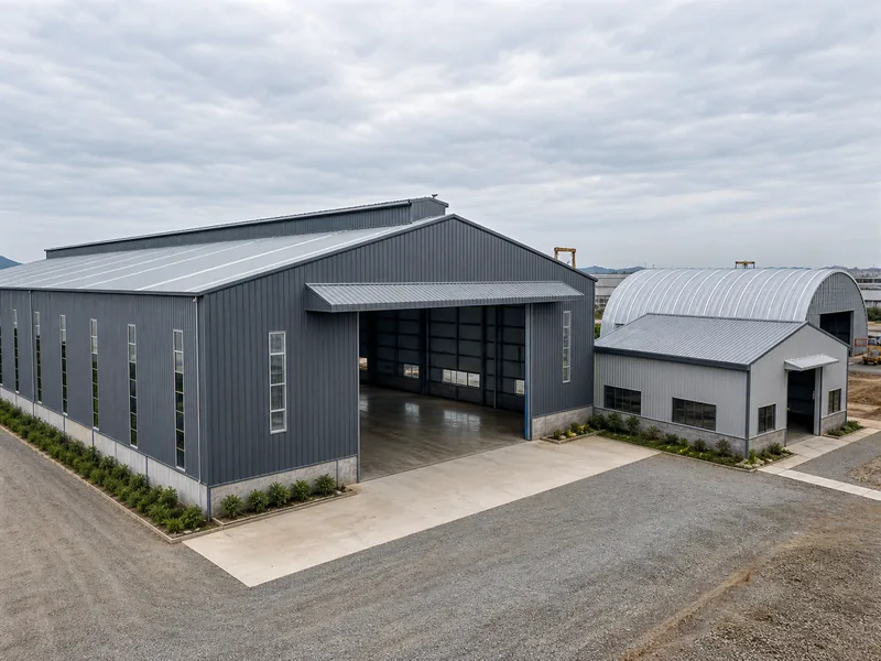
The section you pick also depends on the building around it. Wide, column-free crane bays, the kind found in clear-span buildings, put longer runways and larger moments on the beam, while a framed bay with intermediate columns shortens the spans and eases the section.
Deflection and Fatigue Limits That Govern Design
Deflection, not strength, is usually what sizes a crane runway beam. Excessive vertical sag makes the crane climb and stall, accelerates wheel and rail wear, and feeds the very fatigue that shortens the runway’s life, so the limits are kept tighter than for ordinary beams. Vertical deflection commonly runs from around L/600 for lighter-duty cranes down to L/1000 for severe, continuous service, tightening as the class rises; the exact value belongs to the governing standard and the crane manufacturer’s requirements, not to one universal number.
Lateral deflection deserves separate attention because it often controls deep beams. The top flange of a deep runway beam is relatively narrow, so side-thrust can push it sideways more than the vertical load pushes it down; a common target is on the order of L/400, tighter for high-precision cranes. This is why the channel cap and other top-flange stiffening earn their place in the design.
Fatigue is the check that separates a casual runway from a properly engineered one. For higher service classes, connection details have to be selected and detailed against fatigue, because the millions of stress cycles will find any sharp re-entrant corner or poorly terminated weld. Frameworks such as AISC Design Guide 7 and the fatigue provisions of the AISC Specification give the method, while ASCE 7 sets the broader building loads the runway has to coexist with.
Rail, Connections, and Alignment Details
The rail, the connections, and the alignment decide how well a crane beam design performs once the crane is running. The crane rail is sized to the wheel load and fastened so it can expand and resist longitudinal drag without walking out of line. Rail weight increases with crane tonnage, from light sections under small cranes up to heavy sections under high-class ones. Bolted rail clips that allow some movement are generally preferred over rigid welding for production cranes.
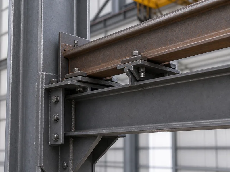
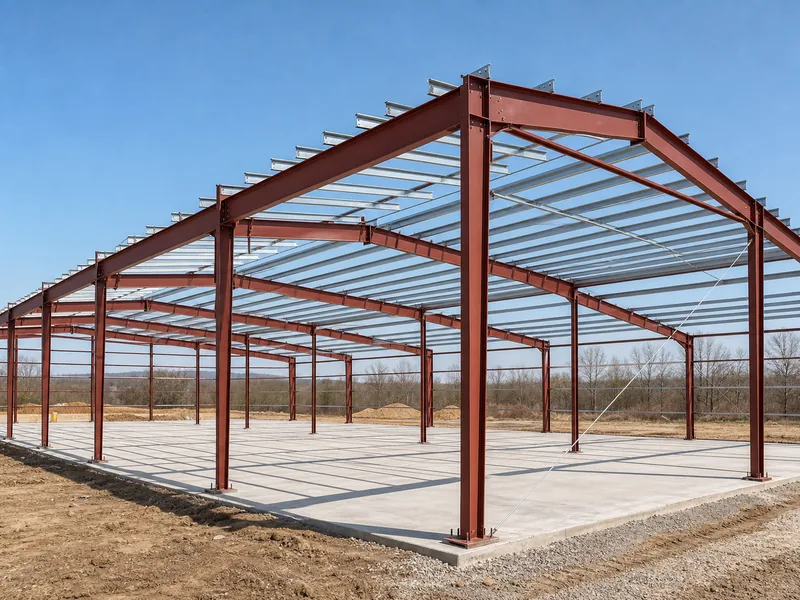
Connections carry the loads the beam collects, and they are where fatigue shows up first. The bracket that ties the runway to the column, the cap plate or seat at the beam end, and any stiffener welds all see the cyclic load, so they are detailed to spread stress rather than concentrate it. A crane beam supported by a heavy structural frame, the red iron framing typical of industrial steel buildings, relies on that frame and its brackets to carry the thrust down to the foundation.
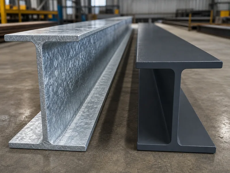
Alignment is the detail most often underestimated. Runway tolerances are held to millimeters (span between rails, rail elevation, straightness, and joint mismatch) because a runway that drifts out of tolerance forces the crane to skew, which spikes the lateral load and the wear it was meant to avoid. The exact tolerances belong to the governing standard such as CMAA 70 or ISO 12488; the design intent is simply that small misalignments have outsized consequences under a moving, repeating load. Industrial workshops and the other types of metal buildings that run cranes should budget for an alignment survey, not assume the steel arrives perfectly straight. Surface protection belongs on the same checklist, since a runway beam is hard to recoat once the crane is live; whether to specify galvanizing or a paint system is a genuine durability decision in exposed or corrosive bays.
Before sizing anything, confirm these inputs first:
- Crane service class and duty cycle
- Wheel loads plus the impact allowance
- Lateral and longitudinal forces
- Vertical and lateral deflection limits
- Fatigue category for the connections and the rail alignment tolerance
Approaching Your Crane Beam Design With Confidence
A crane beam is best designed in order: fix the crane’s service class and loads first, choose the section second, and verify deflection, fatigue, and alignment last. Reversing that order, picking a section before the class and loads are settled, often leads to late redesign, because the class already decides the deflection limit and whether fatigue governs the connections. Once those are locked, the choice between a rolled H, a capped built-up beam, or a box girder follows from span and wheel load, and the verification checks confirm the section rather than reshape it.
The part that rewards experience is the interaction between those steps: a deeper section helps vertical deflection but can worsen the lateral problem, a channel cap fixes the top flange but makes the bending biaxial, and a heavier rail eases wheel-load stress but adds dead weight the beam must carry. Working these trade-offs with experienced steel building contractors that can coordinate design review and fabrication, supplying a welded H or box girder when the loads call for it, keeps the beam, the connections, and the rail consistent with one another. The number to design to is never just the lifted tonnage; it is that tonnage, amplified by impact, repeated by the cycle count, and held within the deflection your crane class allows.
FAQs
How is a crane runway beam different from a regular steel beam?
A crane runway beam is designed for moving, repeating loads, so deflection and fatigue usually govern it rather than static strength alone. The beam carries wheel loads that travel along its length thousands of times, plus lateral thrust and impact, which a static floor or roof beam never experiences.
What deflection limit applies to a crane runway beam?
Vertical deflection limits for crane runway beams commonly range from about L/600 for lighter-duty cranes to L/1000 for severe service, tightening with the crane’s service class. Lateral deflection of the top flange is often held near L/400. The governing standard and the crane manufacturer set the exact value for any given project.
Do all crane beams need an explicit fatigue check?
Fatigue normally has to be checked for busier cranes and may not govern for the lightest, most infrequent ones. Higher CMAA service classes see millions of stress cycles, so their connection details are typically governed by fatigue; standby and light-duty runways are more often controlled by strength and deflection, subject to the project’s design criteria.
Which steel section is best for a crane girder?
The best section depends on span, crane weight, and service class, not on a single answer. Hot-rolled H-sections suit shorter, lighter runways; welded H-sections, channel-capped beams, and box girders suit longer spans and heavier or higher-class cranes; truss runways suit very long spans.