




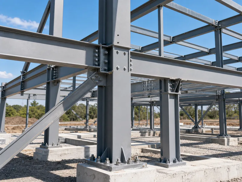
A steel structure connection is the joint that moves force from one member into another, and how well it does that decides whether the frame stands or sways. Connections are grouped two independent ways, and the two are easy to confuse even though they answer different questions. The first grouping is the joining method: what physically holds the members together, namely bolts, welds, or rivets. The second is structural behavior: how much the joint restrains rotation, which sets whether it passes only shear, full bending moment, or axial load. A joint can be bolted or welded and still be either a simple joint or a moment joint, so the hardware alone does not tell you how the connection behaves.
This article covers those connection types and the logic for choosing between them. It does not walk through weld-procedure specifications, clause-by-clause code design, or how anchor bolts are set in concrete on site.
What a Steel Structure Connection Has to Do
Every steel connection carries some combination of three forces between members: shear, bending moment, and axial load. Which of those forces a joint must transfer is decided in the structural model, before anyone chooses a bolt or strikes an arc. Get that intent wrong and the detail follows it wrong, no matter how neat the fabrication looks.
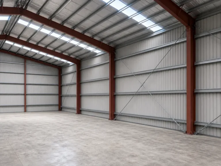
The common mistake is to treat “bolted versus welded” and “pinned versus rigid” as the same choice. They are two separate axes. Bolting and welding describe how the steel is fastened; simple, moment, and bracing describe how the joint behaves under load. You can weld a joint that is meant to rotate freely, and you can bolt a joint that has to transfer full moment. On a portal-frame building, for example, the eaves and apex are detailed as moment connections, while the purlin and girt cleats stay simple. That split holds whether the shop bolts those joints or welds them. So the first question at any node is not “bolt or weld” but “what does this joint have to resist.”
Steel Connection Types by Joining Method
By joining method, steel connections fall into three families: bolted, welded, and riveted. The first two carry nearly all new construction; the third is mostly something you inherit.
Bolted connections
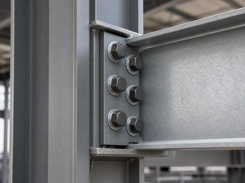
Bolted connections fasten members with high-strength bolts and are the workhorse of field assembly, because crews can make them fast and check them by eye and by torque. The common high-strength grades are 8.8 and 10.9 under European designations, or A325 and A490 grades in North American practice. Bolted joints behave in one of two ways. A bearing-type joint lets the bolt shank bear against the side of the hole, which is the economical default. A slip-critical, or friction-type, joint is pretensioned so the clamped plates carry load by friction before any slip occurs, which is what you specify where load reverses or fatigue matters. Either way, the joint is only as good as its installed tension, so pretension is verified by turn-of-nut or by direct-tension-indicator washers rather than assumed.
Welded connections
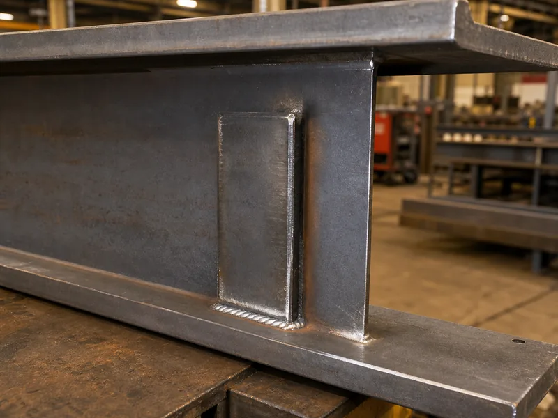
Welded connections fuse members with deposited weld metal and can develop close to the full strength of the section being joined. Two weld types cover most work. Fillet welds run along the edge of lapped or T-joined plates. Groove (butt) welds fill a prepared gap and, when full-penetration, transfer the member’s full force. Welding is preferred in the shop, where the work can be positioned flat, controlled, and inspected. Field welding fights position, weather, and access, so it is reserved for joints that genuinely need it. Critical welds are checked beyond a visual pass, using ultrasonic or radiographic testing, and structural steel welding itself is governed by AWS D1.1 in North American practice. Most fabricators therefore weld in the shop and bolt in the field, because a shop weld is made under control while a field weld is made under whatever the site offers.
Riveted connections
Riveted connections belong mostly to older structures, and new steel buildings almost never use them. Hot-driven rivets once did the job that high-strength bolts do now, and they were largely replaced because bolting is faster, quieter, and easier to inspect. You meet rivets today mainly when assessing or retrofitting heritage steelwork, where matching the original joint behavior matters more than the fastener itself.
Steel Connection Types by Structural Behavior
Structural behavior splits connections a second way: a joint is simple, moment, or bracing depending on how much it restrains the members, regardless of whether it is bolted or welded. This is the axis that governs how the frame as a whole resists load, so it helps to read a joint by its behavior before its hardware.
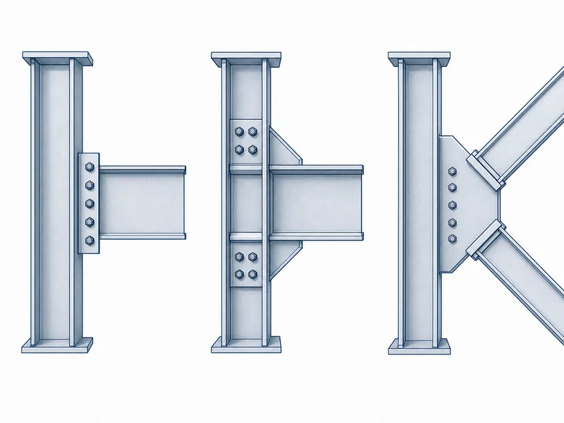
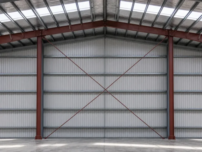
A simple connection transfers shear and lets the connected members rotate, so it carries vertical load without holding the angle between members. Fin plates, flexible end plates, and seated cleats are typical, and they suit braced frames where bracing or shear walls take the lateral load. A moment connection transfers bending as well as shear and keeps the angle between members fixed. That fixity is what lets a frame resist sway through frame action alone, as at the eaves of a portal frame. Moment joints use more material and more fabrication, so they are specified where they are needed, not by default. A bracing connection carries axial tension or compression along the brace line and usually lands on a gusset plate at the brace end. How those braces are laid out across a bay is the subject of steel frame bracing. The two axes connect directly: if a bay has no bracing, its beam-to-column joints must be moment connections, or the frame is a mechanism, so the model’s braced-versus-moment decision dictates the joints you detail.
Design codes formalize this. Eurocode 3 (EN 1993-1-8), for instance, classifies joints by stiffness and strength and lets a joint be treated as nominally pinned when its moment resistance is small compared with that of a full-strength joint.
Where Connections Sit in a Steel Frame
Most steel frames reuse the same handful of connection locations, and each one ties specific metal building framing components into a continuous load path. Naming them is what makes a structural drawing legible.
- Beam-to-column: the everyday joint where a beam frames into a column, detailed as simple or moment depending on the frame.
- Beam-to-beam: secondary beams framing into primary beams, usually simple shear joints.
- Column splices: where one column length joins the next in taller frames, made with bolted cover plates or end plates.
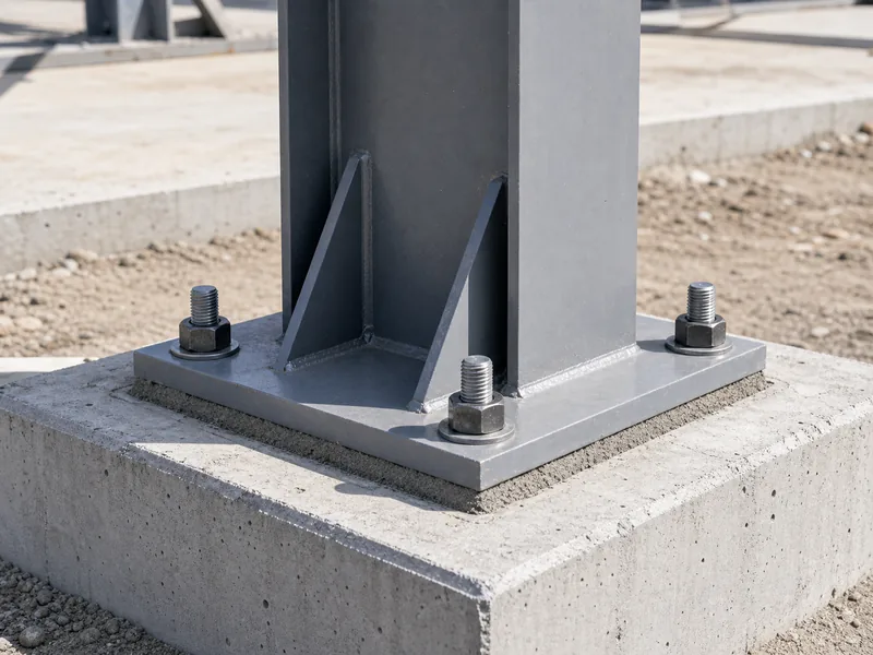
- Column bases: a base plate welded to the foot of the column and fastened to the concrete with anchor bolts. The base plate spreads the column load across the concrete, and the anchor bolts resist uplift and shear. This is the handoff from steel to the metal building foundation, and whether the base is detailed as pinned or fixed changes how much moment passes into the footing.
- Bracing connections: brace members meeting the frame at gusset plates, sized for axial load.
Choosing Between Bolted and Welded Connections
Choosing between bolted and welded connections is mostly a question of where the work happens and what the joint has to resist. The two methods are not rivals so much as tools for different settings, and most buildings use both.
| Factor | Bolted | Welded |
|---|---|---|
| Best setting | Field erection | Shop fabrication |
| Speed on site | Fast, immediate | Slower; setup, weld, and inspection |
| Inspection | Visual plus torque or tension check | Visual plus NDT on critical welds |
| Load reversal and fatigue | Slip-critical bolts handle it well | Good if detailed for fatigue; weld toes can crack |
| Removability | Demountable | Permanent |
| Typical home | Beam-to-column, splices, field braces | Built-up sections, base plates, full-strength moment joints |
For most steel buildings the practical answer is both: weld the heavy connection elements in the shop, then bolt the assembled pieces together in the field. At the building scale, that same trade-off appears as the choice between weld-up or bolt-up steel buildings.
Cost is the reason this choice matters. Connections add very little steel weight but a great deal of labor. In a typical braced multi-storey frame, connections may be under 5% of the frame’s steel weight yet account for 30% or more of its cost. Connection fabrication alone can run 30 to 50 percent of total fabrication cost, according to UK steel industry guidance published on SteelConstruction.info. Standardizing and simplifying connection details therefore lowers a steel frame’s price more than shaving member sizes does, which is why repeatable bolted details are favored over one-off field welds.
Where Steel Connections Fail and How They’re Checked
Connections fail in a handful of predictable ways, and most are caught by checks that cost far less than the repair. Each failure mode has a matching verification, and the pattern is always the same: a variable left unconfirmed becomes a defect that a routine check would have flagged.
- Under-tightened or wrong-grade bolts lose the clamping force a slip-critical joint relies on, so installed pretension and bolt markings are verified rather than trusted.
- Weld defects such as lack of fusion, porosity, or undersized fillets cut strength and seed fatigue cracks, so full-penetration and critical welds get ultrasonic or radiographic testing on top of a visual pass.
- Fatigue and stress concentration gather at weld toes and re-entrant corners under repeated load, as under crane runways, so those details are designed for fatigue and ground smooth where the spec calls for it.
- Corrosion at faying surfaces eats section where you cannot see it, so joints exposed to moisture are sealed, coated, or galvanized and detailed to drain. Near the coast, the faying surfaces and any pocket that traps water are the first places section loss starts, well before it shows on the surface.
- Misalignment and tolerance force a fit-up and lock stress into the joint, so connection details and their tolerances are checked against the structural drawings before steel reaches site. Reading those callouts is covered in reading steel structural drawings.
Conclusion
Detailing a steel connection follows an order: first the behavior, then the method, then the check. Decide first what the joint has to do, because the structural model, not the hardware, says whether a node only passes shear or has to transfer moment and hold the frame’s geometry. Choose the joining method second, matching it to how the work is built, with shop welding for built-up and full-strength elements and field bolting for speed and demountability. Fix the verification last, scaling bolt-tension checks or weld NDT to how much the joint carries.
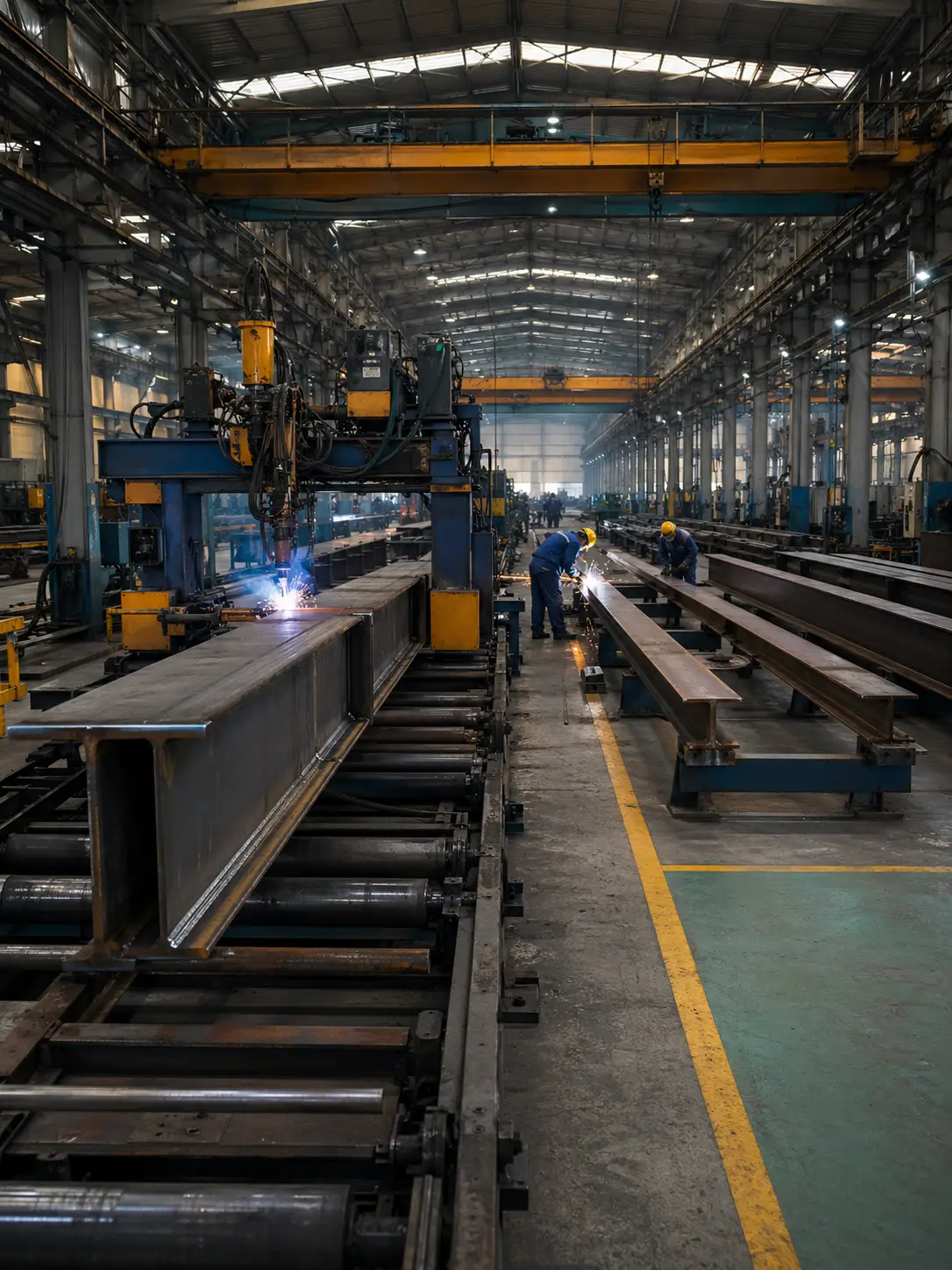
The same three calls sit underneath how you design a steel building, where the connection scheme is settled alongside the framing rather than after it. At KAFA, the H-beam, box-section, and purlin lines cut, drill, and weld connection elements such as base plates, end plates, and gusset plates under one roof, which leaves field work mostly to bolting. Get the moment-versus-shear call right at each node, and the rest, from bolt grade to weld type to base-plate anchorage, follows from it.
FAQ
What are the three main types of steel structure connections?
By joining method, the three types are bolted, welded, and riveted connections, though riveting is now confined mostly to older structures. Modern steel buildings run on bolted and welded joints, and a single building usually uses both: members are often welded in the shop, then bolted to one another in the field.
What is the difference between a simple and a moment connection?
A simple connection transfers shear and lets the members rotate, while a moment connection also transfers bending and holds the angle between members fixed. Simple connections suit braced frames, where bracing or walls resist lateral load, whereas moment connections appear where the frame itself must resist sway, such as at the eaves and apex of a portal frame.
Are bolted or welded connections stronger?
Neither is inherently stronger, because a correctly designed bolted joint and a correctly designed welded joint each develop the strength the member needs. The real differences lie in where they are made, with welding favored in the shop and bolting in the field, and in how they are inspected and how they behave under fatigue.
What connects a steel column to its foundation?
A steel column meets its foundation at a base plate fastened to the concrete with anchor bolts. The base plate spreads the column load across the concrete and the anchor bolts resist uplift and shear, and whether the base is detailed as pinned or fixed changes how much moment it transfers into the footing.
Can a single connection use both bolts and welds?
Yes, hybrid connections combine welds and bolts, typically welded in the shop and bolted on site. A common example is a beam with a shop-welded end plate that is then field-bolted to the column. The aim is to keep the load path clear, so that one method governs each force the joint carries.
Further Reading
- American Welding Society (AWS D1.1 Structural Welding Code, Steel): the US authority governing structural steel welding, behind the welded connections described above.
- SteelConstruction.info: Simple connections (BCSA / SCI): UK steel industry guidance on connection types, simple-versus-moment classification, and the cost share of connections.
- Eurocodes: EN 1993 (Eurocode 3, design of steel structures): the European Commission JRC portal for the code that governs steel joint design and classification (EN 1993-1-8).