




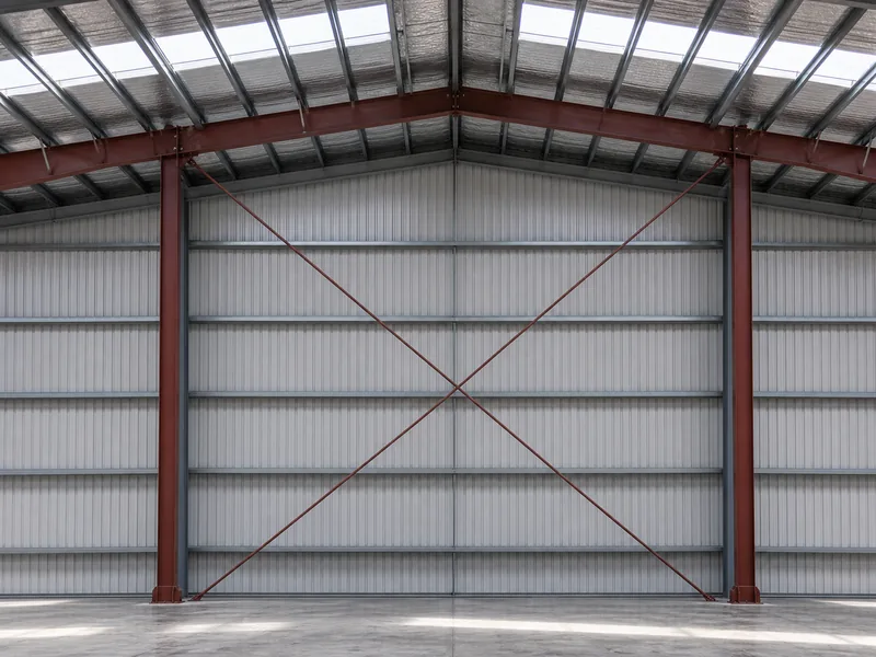
Cross bracing is a pair of diagonal steel members set in an X across one bay of a frame, and it exists to carry sideways loads — mostly wind and earthquake — safely down to the foundation. Push a bare rectangle of columns and beams from the side and it racks, leaning over into a parallelogram. Add the two diagonals and the bay becomes a triangle that resists that movement, with one diagonal stretching in tension while the other shortens in compression. Together they hold the frame square, which is why braced bays appear in almost every steel warehouse, workshop, and industrial frame.
The sections below explain how that load path works, the main configurations you will see on a steel building, where the bracing sits in the structure, the materials it is cut from, and how the right system is chosen. Cross bracing is one of the metal building framing components that does the bulk of its work only a few days a year, during the strongest storm or the largest seismic event the building will face.
How Cross Bracing Carries Lateral Loads
A cross brace splits every sideways push into a pull along one diagonal and a shove along the other. Gravity loads travel straight down the columns, but wind against a wall, or ground motion under the footings, tries to slide the top of the frame sideways relative to the base. The diagonal running from the loaded corner up to the far top corner goes into tension; the opposite diagonal goes into compression. Both ends connect into the column-to-beam joints, so the horizontal force becomes axial force in the steel and is delivered to the base plates and anchor bolts.
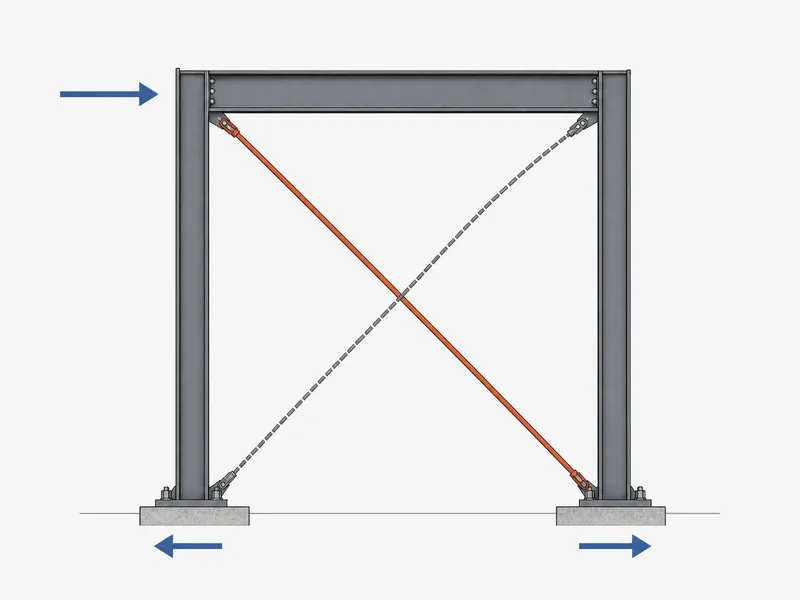
Wind and seismic forces reverse direction, and the bracing has to answer in both. When the wind swings to the other wall, the diagonal that was pulling is now pushing, and the other does the opposite. A single X handles this neatly because it already carries a diagonal for each direction. How large those forces get is set by the building’s exposure and geometry, which is the realm of the wind loads and seismic demand the frame is designed against. In a crane building, the horizontal surge from the moving bridge and trolley feeds into the same braced bays.
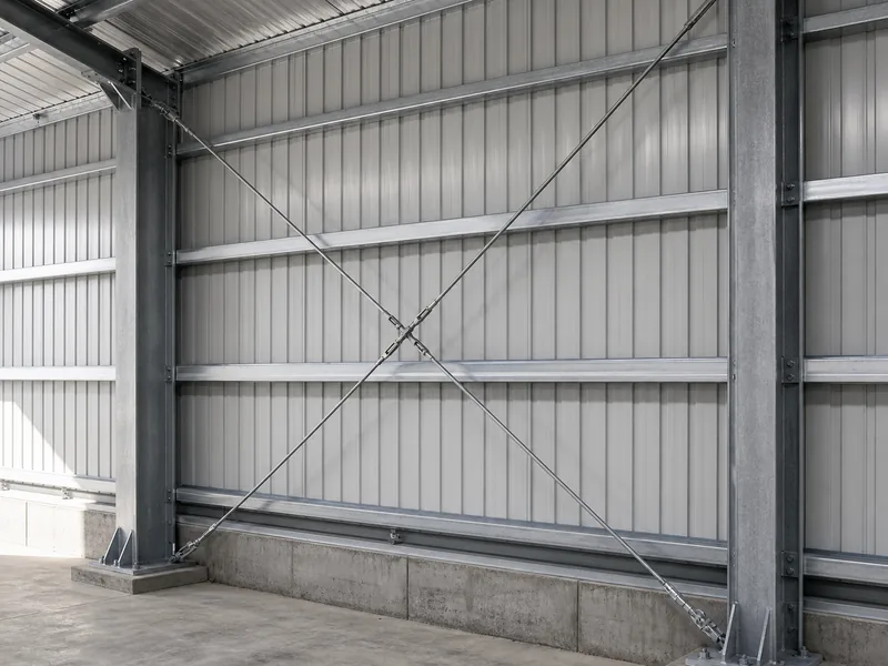
Slender braces only pull. Many light steel buildings use thin round rods or steel cables as the diagonals, and those carry tension well but buckle instantly under compression. The system still works: when the load reverses, the slack diagonal goes along for the ride while its partner takes the full tension. This arrangement is called tension-only bracing, and it is the reason you often see a thin crossed rod where a heavier single strut would otherwise sit.
The Main Types of Cross Bracing and Close Relatives
True cross bracing is the X-pattern, but several related diagonal layouts solve the same lateral-load problem with different trade-offs. The choice usually turns on one practical question: does the wall need a clear opening for a door, window, or equipment, and where? The table sums up the everyday options before the detail below.
| Configuration | Shape | Opening in the bay | Notes |
|---|---|---|---|
| X-bracing (cross) | Two full diagonals | None; the bay is blocked | Stiffest for the steel used; common in rods or angles |
| Single diagonal | One diagonal | Partial | Must resist tension and compression, so a stockier section |
| K-bracing | Diagonals to mid-column | Doorway-height opening | Restricted in high-seismic design |
| V / chevron | Diagonals to mid-beam | Opening under the apex | Beam must carry the unbalanced force |
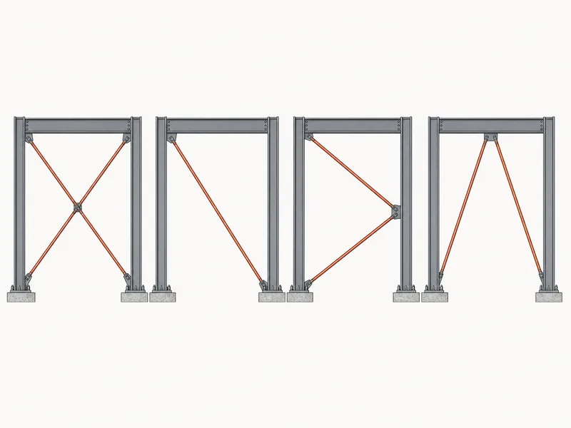
X-Bracing (True Cross Bracing)
X-bracing places two full diagonals across the bay, so one is always in tension whichever way the load runs. It gives the most stiffness for the weight of steel, which is why it is the default in many braced frames. The cost is access: a bay with a full X cannot also hold a large door or window, so these bays go where the wall can stay solid.
Single Diagonal Bracing
Single diagonal bracing uses one member per bay instead of a crossed pair. Because that lone diagonal has to push in one wind direction and pull in the other, it is usually a heavier angle, channel, or tube that will not buckle in compression. The payoff is a partly open bay, useful when a full X would block something the floor plan needs.
K-Bracing
K-bracing runs two diagonals from the top and bottom of one column to a point near the mid-height of the next, forming a sideways K. The shape leaves a clear opening over much of the bay height, which is its main appeal. Design codes restrict K-bracing in regions of high seismic demand, because the diagonals push and pull on the middle of the column and can drive it to fail; that limit is why it shows up more in wind-governed buildings than in earthquake country.
V-Bracing and Chevron Bracing
V-bracing sets two diagonals that meet at the mid-span of a beam, forming a V or an inverted V (chevron). The apex leaves room for a doorway beneath it, so it is common over corridors and openings. The catch is the beam at the meeting point. When one diagonal buckles in compression, the other keeps pulling, so the beam has to carry the leftover unbalanced force and is sized for that case rather than as an ordinary purlin-supported member.
Where Cross Bracing Goes in a Steel Building
Bracing is concentrated in a few chosen bays rather than spread across every frame, and it works in two planes at once. The first plane is vertical: crossed diagonals set between two columns in selected wall bays, usually including the end bays, carry horizontal load down to the foundations. The second plane is the roof, where horizontal or plan bracing laid in the plane of the roof collects wind from the gable posts and the long walls and drags it back to those vertical braced bays. The two planes form a continuous path from the cladding to the ground.
Roof bracing also steadies the frame during erection and gives the purlins a stiff line to anchor against, which is why it is fitted early in the build. In a portal frame building, the rigid frames resist sideways load across the width of the building on their own, but they do little for movement along its length. Bracing fills that gap, providing longitudinal stability down the length of the structure and holding everything steady while the frames are stood up. Because braced bays need a solid wall, they sit away from the largest roller doors, and the diagonals are often hidden inside the wall build-up once the cladding goes on.
Materials and Connections Used for Cross Bracing
The diagonal itself can be a round bar, a steel angle, a channel, a hollow tube, or a tensioned cable, and that choice sets whether the brace can push as well as pull. Rods and cables are tension-only and are usually fitted with a turnbuckle so the erector can take up the slack and pre-tension them on site. Angles, channels, and hollow sections can also carry compression, so they suit single-diagonal and chevron layouts where one member has to do both jobs.
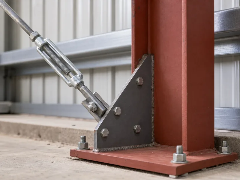
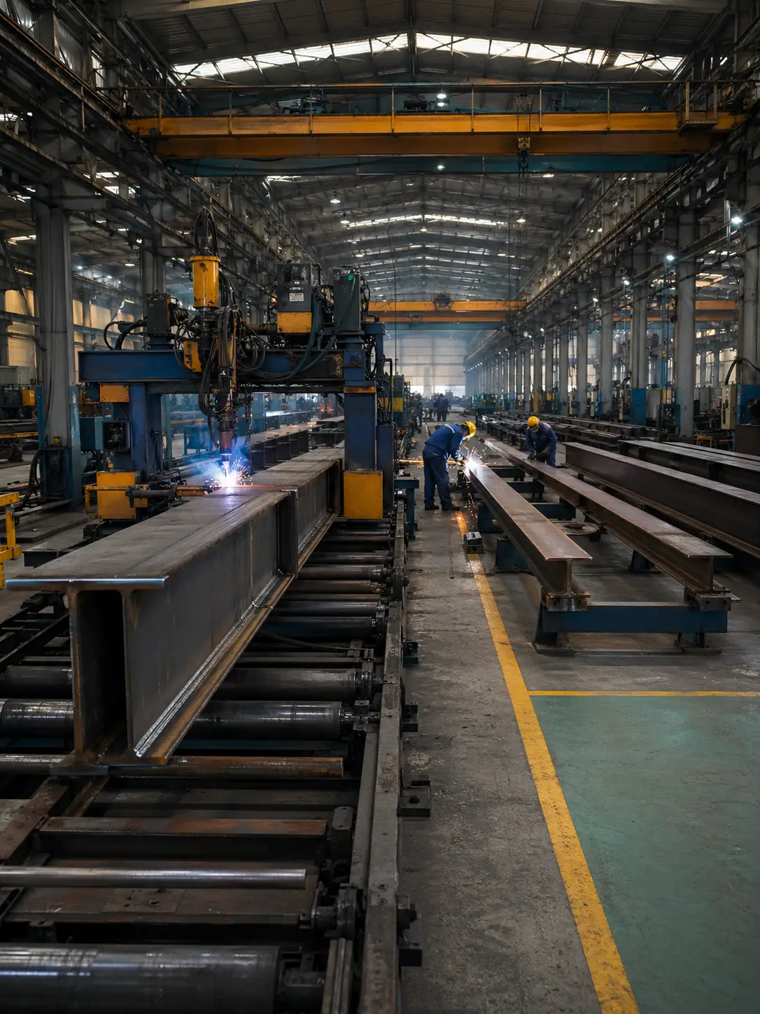
Connections decide whether the brace force actually reaches the foundation. Each diagonal lands on a gusset plate that is bolted or welded to the column, the rafter, or the base plate, and that joint has to be sized for the full brace force, not just the member. A weak gusset or an undersized anchor bolt becomes the limit of the whole load path. The braces tie into the primary frame: the H-section columns, box-section members, and C- and Z-section purlins that a fabricator such as KAFA produces on dedicated lines, so the bracing is detailed alongside those members rather than added afterward.
Choosing the Right Bracing and Keeping It in Place
The right bracing system follows from three inputs: the lateral loads, the frame layout, and where the building needs clear openings. Heavier wind or seismic demand pushes toward stiffer X-bracing or specially detailed braced frames, while a wall full of doors pushes toward single-diagonal, K, or chevron layouts that leave the openings clear. Those demands come out of the load calculations for the site, and the bracing is then sized as part of the overall building steel design rather than picked from a catalogue, so that members, gusset plates, and anchor bolts share one consistent load path.
The most common bracing problem on existing buildings is not design but removal. Crews cut a diagonal to fit a new door, window, or extension and never put an equivalent load path back, which leaves the frame relying on connections that were never meant to resist that sway alone. The tell-tales are easy to read once you know them: empty bolt holes where a brace used to land, or a diagonal that a forklift has knocked and bent. Before altering any braced bay, find it on the structural drawings and have the load path re-established by the engineer, not patched over.
Conclusion
Cross bracing keeps a steel frame from leaning over under wind and earthquake, so the first move on any building is to identify which bays are braced and trace where their load goes. Pick the configuration around the openings the building actually needs: a full X where the wall can stay solid, or a single diagonal, K, or chevron where it cannot, and size the diagonals, gussets, and anchors as one connected path. Above all, treat an existing brace as load-bearing, and never cut or move one to make room for a door without an engineer restoring the bracing the frame was designed around.
FAQ
What is the purpose of cross bracing in a building?
Cross bracing keeps a building from racking sideways under horizontal loads. It gives the frame a triangulated path that carries wind, seismic, and crane forces from the walls and roof down to the foundations, limiting sway and protecting the cladding and connections from damage. Without it, a rectangular steel frame would lean and distort under loads the columns alone cannot resist.
Is cross bracing in tension or compression?
Both, at the same time. In a crossed pair, one diagonal is in tension while the other is in compression, and the two swap roles when the load reverses direction. Thin rod or cable braces are the exception, since they carry tension only: the slack diagonal drops out and its partner takes the full pull each time the wind changes sides.
What is the difference between cross bracing and K-bracing?
Cross bracing forms a full X across the bay, while K-bracing runs two diagonals to the mid-height of a column to leave an opening clear. The X is stiffer and works in either load direction but blocks the bay; the K frees up door height but is restricted in high-seismic design because its diagonals load the middle of the column.
Can you remove cross bracing to add a door or window?
Not without redesign. A braced bay is part of the building’s lateral load path, so cutting a diagonal removes capacity the frame was counted on to have. If an opening has to go where a brace sits, an engineer needs to relocate the bracing to another bay or add an equivalent system, then re-detail the connections, before the original brace comes out.
What materials are used for cross bracing?
Cross braces are made from round bars, steel angles, channels, hollow tubes, or steel cables. Rods and cables are tension-only and are usually tensioned with a turnbuckle, while angles, channels, and tubes can also take compression, which suits single-diagonal and chevron layouts. The diagonals connect to the columns and rafters through bolted or welded gusset plates sized for the full brace force.
Further Reading
- Braced frames — SteelConstruction.info — SCI and BCSA steel knowledge base. Explains vertical and horizontal bracing systems and how crossed diagonals stabilise a braced frame.
- Portal frames — SteelConstruction.info — SCI and BCSA. Covers how vertical and plan bracing provide longitudinal and erection stability in single-storey steel buildings.
- ASCE 7 standard — ASCE — American Society of Civil Engineers. The standard that sets the minimum wind and seismic design loads a bracing system must resist.