A steel structure load calculation adds up every force a building has to carry: its own weight, the people and equipment inside it, and the wind, snow, and seismic effects from outside. Those forces are then combined under a code such as ASCE 7 so each member, connection, and foundation can be checked against the result. The output is not a single number. It is a set of load cases, and the heaviest case for any given part decides how much steel that part needs. This guide walks through the load types that matter, the codes that set their values, how the loads are combined, and how those combinations turn into the member checks a design can actually be held to.
What a steel structure load calculation actually covers
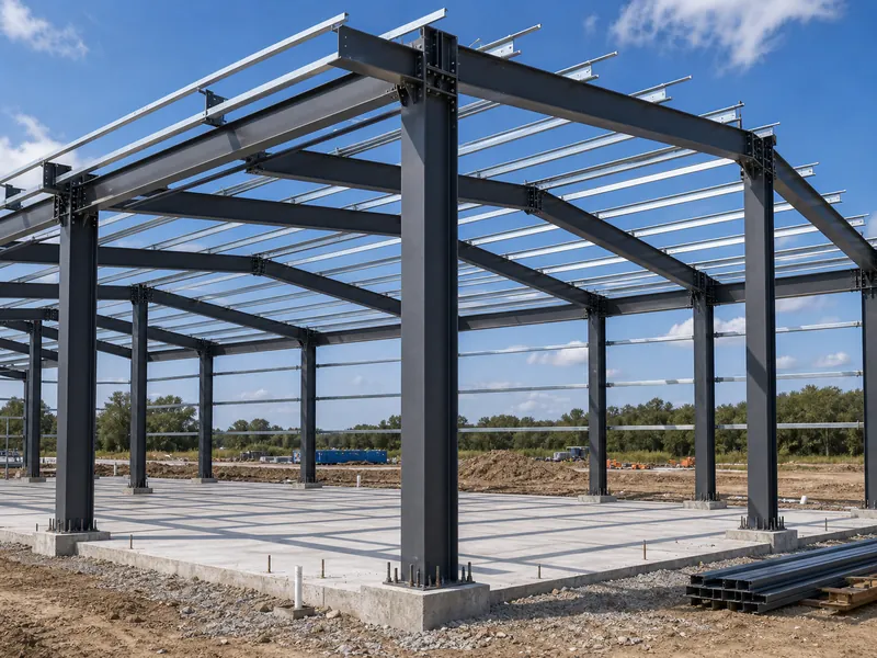
A complete load calculation begins by listing every load path in the building, not just the obvious roof and floor weights. Loads fall into four families: permanent loads that never move (the frame and cladding), variable loads tied to how the building is used (occupants, stored goods, suspended services), environmental loads from the site (snow, wind, rain, and earthquakes), and equipment loads such as cranes. Miss one family and the rest of the math is built on a short total.
The step that owners underestimate most is collateral load, the weight of everything hung from the frame after the steel is up: HVAC ducts, sprinkler lines, and ceilings. It is invisible on a framing drawing, but it is permanent, and it has to be carried for the life of the building.
This article covers how loads are determined and combined. Sizing an individual beam, detailing a connection, or designing reinforcement is a separate stage of the steel building design process and is not the focus here.
The load types that shape a steel structure
Seven load types cover almost every steel building: dead, collateral, live, snow, wind, seismic, and crane. The table below shows what each one includes, a typical industry range where one exists, and the variable that moves the number.
| Load type | What it includes | Typical industry range | Key variable |
|---|---|---|---|
| Dead | Frame, fixed cladding, roofing | ~5–8 psf (8–10 with heavy MEP) | Framing and panel choice |
| Collateral | Suspended HVAC, sprinklers, ceilings | ~5–10 psf | Services hung from the frame |
| Live (floor) | Occupants, movable equipment | 50 psf office to 125 psf+ warehouse | Building use (occupancy) |
| Roof live | Maintenance access | 20 psf minimum | Reducible for large areas |
| Snow | Accumulated and drifted snow | Set by site ground snow load | Location, roof slope, exposure |
| Wind | Pressure, suction, and uplift | Varies with speed and exposure | Basic wind speed, exposure |
| Seismic | Inertia from ground motion | Set by site spectral values | Seismicity and building mass |
| Crane | Forces from lifting equipment | Set by crane rating | Crane type and capacity |
Treat those as illustrative industry ranges, not design values. The figure that ends up on the drawings depends on the site’s ASCE 7 data, the occupancy, and the building geometry. It does not replace ASCE 7, the local code, or the engineer of record who signs the calculation for the project.
Occupancy is what separates one building’s live load from another’s. For a commercial steel building, a retail or office floor is designed to a far lighter live load than a warehouse bay built for racking and forklifts, even when the two share an identical frame. Get the assumed use wrong and the floor is either over-built or unsafe. Environmental loads behave differently again, which is why live load, dead load, and snow load are quantified from separate sources rather than a single rule of thumb.
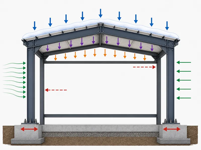
Wind is the load that governs more often than first-time owners expect, especially for tall, open, or coastal buildings, because it acts as both inward pressure and outward suction. A lightweight steel roof weighs little, so wind uplift can try to lift the structure off its anchors; the detailed wind load case usually deserves its own attention. Buildings with overhead lifting add a crane load that brings vertical, lateral, and longitudinal forces the bare frame never sees.
The codes that set the load numbers
In the United States, four documents do most of the work behind a steel structure load calculation. ASCE 7, *Minimum Design Loads and Associated Criteria for Buildings and Other Structures*, sets the magnitudes for dead, live, snow, wind, and seismic loads and defines how they are combined. The International Building Code (IBC) adopts ASCE 7 into law and assigns each building a Risk Category from I to IV, so an essential facility like a hospital is designed to more conservative loads than a storage shed.
AISC 360, the *Specification for Structural Steel Buildings*, takes over once the loads are known: it governs how each steel member and connection is checked, using either the LRFD or ASD method. For metal building systems specifically, the Metal Building Manufacturers Association (MBMA) publishes worked methods for wind, snow, seismic, and crane loads that align with the current IBC and ASCE 7 editions.
These four set the framework, but they are U.S. references. A project in Europe or Asia follows its own code, such as the Eurocodes or a national standard like GB, and the load values do not transfer between systems. The principle is the same everywhere; the numbers are not.
How loads get combined: LRFD and ASD
Loads are never simply added at full value, because the heaviest live load and the strongest wind rarely peak in the same instant. Instead, ASCE 7 defines weighted load combinations, and the design has to satisfy the worst one, the governing combination, for each member. Under the LRFD method, representative combinations include 1.4D; 1.2D + 1.6L + 0.5(Lr or S or R); and 0.9D + 1.0W, where D is dead, L is live, Lr is roof live, S is snow, R is rain, and W is wind.
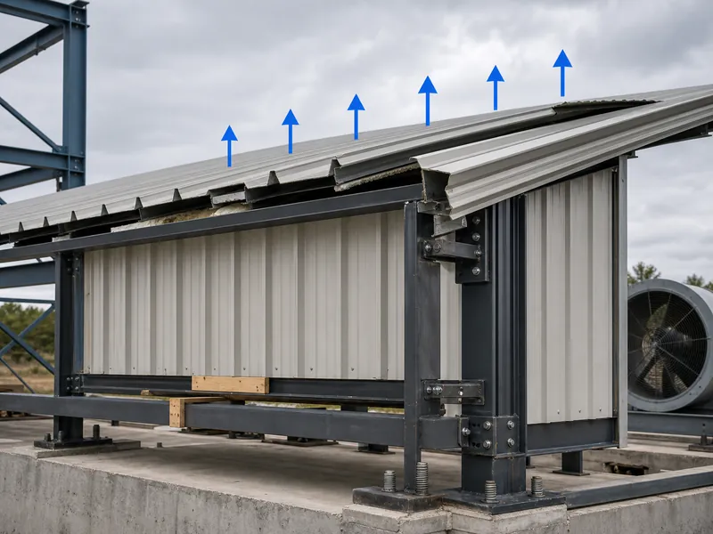
That last combination, 0.9D + 1.0W, is the one that catches light buildings. It pairs reduced dead load with full wind, which is how net uplift shows up: the wind suction overcomes the roof’s own weight and the load on the anchor bolts reverses direction. The combination that controls a light-roof steel building is often the one trying to lift it, not the one pressing down.
ASD, or Allowable Stress Design, is the older approach. It checks service-level loads against allowable stresses that already carry a built-in safety margin, rather than applying separate factors to loads and resistance the way LRFD does. Most modern steel design uses LRFD because it tunes the safety margin to how predictable each load is, but ASD is still valid and still preferred by some engineers for certain checks.
Running the calculation, from site data to member checks
The calculation runs in a fixed order: gather site data, quantify each load, combine the loads, then check members, connections, and the foundation. Skipping straight to a frame size without the first steps is where rules of thumb replace engineering.
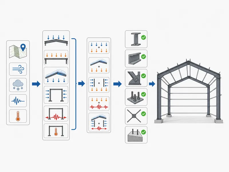
It starts with the site. Tools tied to ASCE 7, such as the ASCE Hazard Tool, return the basic wind speed, ground snow load, and seismic parameters for a set of coordinates, along with the exposure and risk categories. Those site values feed the environmental loads, while dead load comes from a material takeoff and live load comes from the occupancy. Each load is then run through the ASCE 7 combinations to find the governing case for every member.
Only then does member checking begin, and it has two distinct failure modes to satisfy. Strength checks under AISC 360 confirm a member will not break under the governing combination. Serviceability checks confirm it will not deflect too far. A long-span roof beam can pass every strength check and still sag past its deflection limit, which is a common reason a member gets upsized late in design. The same loads then carry down to the steel building foundation, where the anchor bolts have to resist both the downward reactions and the net uplift identified earlier.
Where steel load calculations go wrong
Most load-calculation errors trace back to the inputs, not the arithmetic. The software will faithfully combine whatever loads it is given, so a wrong assumption upstream produces a clean-looking, fully wrong result. A handful of mistakes account for most of them:
- Forgetting collateral load. HVAC, sprinklers, and ceilings get specified after the frame and never make it back into the dead load.
- Misreading exposure or risk category. Calling an open coastal site “suburban,” or vice versa, swings the wind load directly.
- Ignoring net uplift. A light roof checked only for downward load leaves the anchor bolts undersized for the wind case that reverses them.
- Adding roof live load to snow. The two are taken as the larger of the pair, not summed, and confusing that inflates or deflates the roof design.
- Not recalculating after a use change. A warehouse converted to light manufacturing carries new live and collateral loads, but the original load cases often stay on file unchanged.
That last point is where responsibility matters. Final loads, combinations, member and connection checks, and foundation design have to be signed off by a registered engineer of record, working in the code edition and jurisdiction that apply to the building’s location. This guide explains the process; it does not replace that stamped design. As a steel structure manufacturer with in-house design, fabrication, and installation capability, we treat the load basis as the first thing to confirm before any steel is cut. A frame built under an ISO 9001:2015 quality system is only as correct as the load cases it was sized for.
Conclusion
Before you trust a steel structure load calculation, lock down three inputs first: the site’s ASCE 7 wind, snow, and seismic data; the real occupancy plus anything hung from the frame; and the risk category tied to how the building will be used. With those three fixed, the governing load combination and the member, connection, and uplift checks follow from the code rather than from guesswork. The expensive surprises tend to come from a changed use or a forgotten collateral load, not from the math itself. When a building’s purpose shifts, the load cases are the first thing to rerun, not the last. A design you can defend is one where every member traces back to a named load case and a stamped set of calculations.
FAQ
How do you calculate the load of a steel structure?
You calculate it by quantifying each load type for the site and occupancy — dead, collateral, live, snow, wind, seismic, and any crane load — then combining them under a code such as ASCE 7 and checking each member against the governing combination. The site values for wind, snow, and seismic come from ASCE 7 mapping tools by location.
What is the difference between dead load and live load?
Dead load is the permanent, unchanging weight of the structure and anything fixed to it, such as the frame, roofing, and cladding. Live load is the variable weight of occupants and movable contents, which is why it is set by how the building is used rather than by the structure itself.
Which code is used for steel structure load calculation?
In the United States, ASCE 7 sets the load magnitudes and combinations, the IBC adopts ASCE 7 into the legal building code, and AISC 360 governs the steel member and connection checks. Metal building systems also follow MBMA methods for wind, snow, seismic, and crane loads.
Is LRFD or ASD better for steel buildings?
LRFD is the default for most modern steel buildings because it matches the safety factor to how variable each load is, which usually yields an efficient design. ASD remains valid and is still chosen for certain checks, so “better” depends on the engineer’s method and the specific case rather than one being universally superior.
Does changing a building’s use require recalculating loads?
Yes. A new use changes the live load and often the collateral load — a storage building converted to manufacturing adds equipment weight and hung services — so the load combinations and every downstream member check have to be redone before the change is safe to occupy.
Further Reading
- ASCE 7-22, Minimum Design Loads and Associated Criteria for Buildings and Other Structures (ASCE/SEI) — the standard that defines the load magnitudes and the load combinations referenced throughout this guide.
- 2024 International Building Code, Chapter 16: Structural Design (ICC) — the code chapter that adopts these loads into law and sets the structural design requirements.
- Metal Building Systems Manual — Design Resources (MBMA) — industry methods for wind, snow, seismic, and crane loads specific to metal building systems.