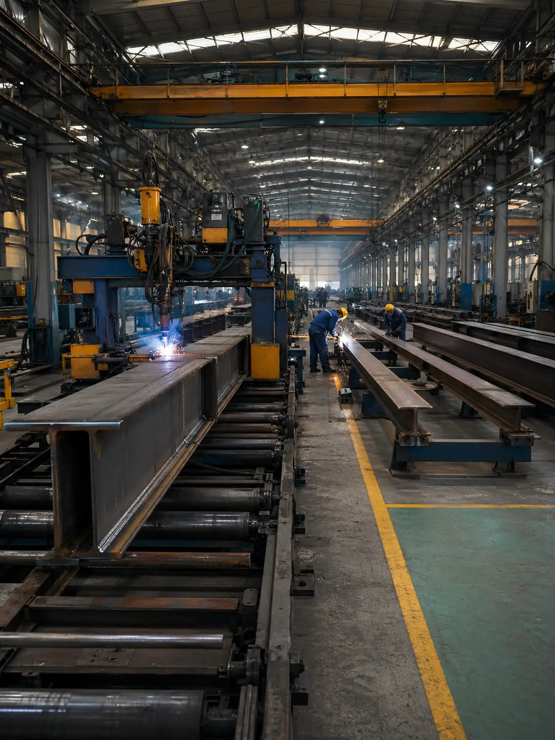





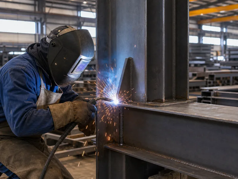
Structural steel welding joins load-bearing members, including columns, beams, base plates, and stiffeners, into one continuous frame by melting their edges so the metal flows together and solidifies as a single piece. Most of that work happens inside a fabrication shop, where built-up sections are made under controlled conditions; out on site, erectors often switch to high-strength bolts for speed and safety. The whole activity is governed by AWS D1.1, the Structural Welding Code for steel, which sets how welds are designed, made, qualified, and inspected. This article covers the processes welders use, the weld and joint types you read off shop drawings, the codes and qualifications behind them, how quality is checked, and when to weld rather than bolt.
What Structural Steel Welding Actually Does
Welding lets a steel building carry load as a single structure rather than a collection of separate parts. An arc melts a small pool of the base metal and adds filler from an electrode or wire; once it cools, the weld metal solidifies as one continuous piece with the members it connects. Because a full-strength weld adds no bolt holes, the joint loses none of the member’s cross-section, which is why a sound weld can be as strong as the beam or column it ties together.
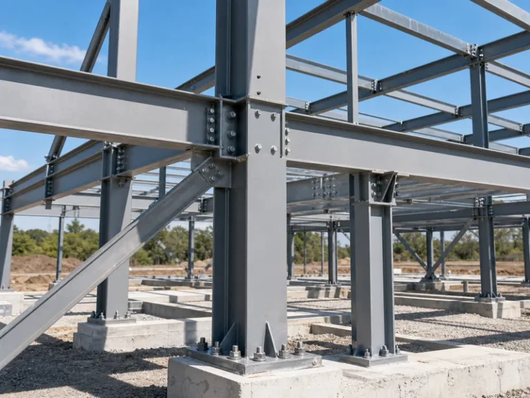
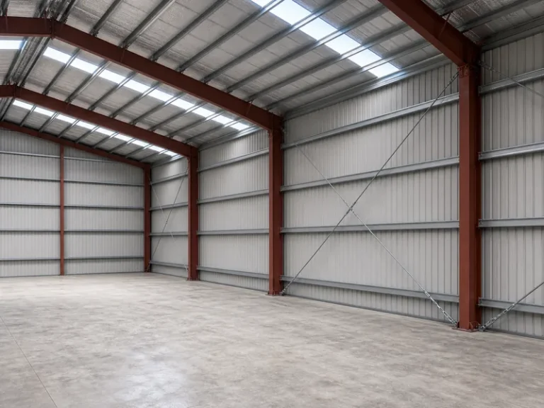
The process does two jobs in a steel frame. It builds the members themselves, since welded H-sections and box sections are fabricated by joining steel plate, and it attaches the connection pieces such as base plates, end plates, cleats, and stiffeners. Welding is therefore how the metal building components of a frame become a rigid assembly instead of loose parts. How those members are joined is decided early, alongside member sizing and bracing, as part of the broader steel buildings designs for the project.
There is a trade-off built into every weld. More penetration and more weld metal add strength, but they also add heat, and heat causes distortion and residual stress in the surrounding steel. Fabricators manage that with joint design, welding sequence, and heat control rather than simply piling on more weld. A manufacturer running dedicated H-beam and box-section welding lines, as KAFA does at its Qingdao plant, sets those sequences once and repeats them member to member.
Welding Processes Used on Structural Steel
Four arc-welding processes cover almost all structural steel work, and the choice among them is mostly a question of whether the weld is made in the shop or in the field. The shop offers shelter, fixturing, and automation; the field demands portability and tolerance for wind and weather.
- Shielded metal arc welding (SMAW), or stick: portable, forgiving of wind and surface contamination, and run with low-hydrogen electrodes such as E7018. It remains a field standby.
- Self-shielded flux-cored arc welding (FCAW-S): generates its own shielding from the wire, so it works outdoors where a gas shield would blow away. It is the field workhorse for production welding.
- Gas-shielded flux-cored welding (FCAW-G) and gas metal arc welding (GMAW/MIG): higher deposition and cleaner welds, but the external shielding gas is sensitive to wind, so they stay indoors.
- Submerged arc welding (SAW): lays down very high deposition under a granular flux blanket and is easily automated, which makes it ideal for the long, heavy welds on built-up sections in a shop.
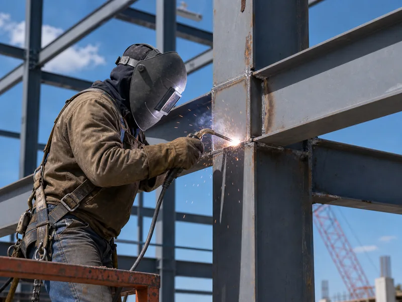
In practice, field crews lean on stick and FCAW-S, while shops favor FCAW-G, GMAW, and SAW. Wind matters because it strips away shielding gas and leaves the molten pool open to the air. An exposed site connection is therefore welded with a self-shielded process or moved indoors. Keeping hydrogen out of the weld through low-hydrogen consumables and dry storage runs through every process, because hydrogen is the root of the cracking discussed below. These process choices feed directly into how a fabricator plans steel frame construction, since they decide what can be prefabricated versus finished on site.
Weld Types and Joints on the Drawings
Fillet welds and groove welds do most of the work in structural steel, and each suits a different joint geometry. A fillet weld has a roughly triangular cross-section laid along the corner where two surfaces meet, needs no edge preparation, and is sized by its leg length. It is the most common weld in structural fabrication because it is fast and economical. A groove weld fills a prepared gap between members, with the edges cut square or shaped into a single or double V, a bevel, a U, or a J for deeper fusion.
Groove welds come in two strengths that matter on the drawings. A complete-joint-penetration (CJP) groove weld fuses through the full thickness and develops the full strength of the connected member, while a partial-joint-penetration (PJP) weld is fused only part way and is specified where full strength is not required. Plug and slot welds handle the occasional case where filling a hole is the only way to make the connection.
| Weld type | Edge prep | Typical use | Strength |
|---|---|---|---|
| Fillet | None | Tee, lap, and corner joints | Sized by leg length |
| Groove (CJP) | Yes | Full-strength butt and tee connections | Develops full member strength |
| Groove (PJP) | Yes | Connections not requiring full strength | Partial, by design |
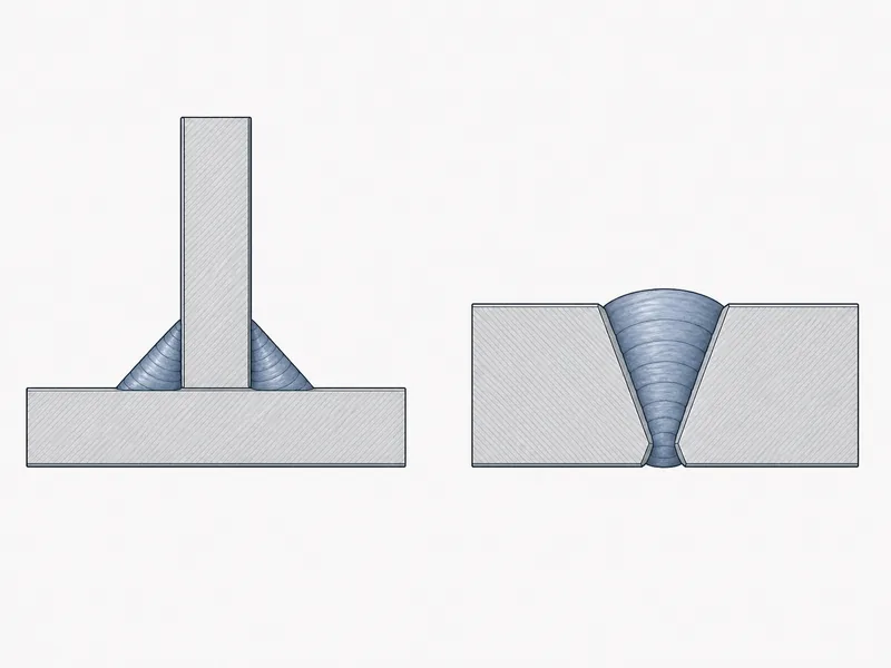
Those welds are applied to five standard joints named in AWS D1.1 and AISC 360, Chapter J: butt, tee, lap, corner, and edge. The welding symbol on a drawing tells the fabricator the weld type, size, length, and location, so being able to interpret it is a prerequisite for the shop floor. If you are new to the notation, start with reading steel structural drawings, since the symbol set drives every weld that follows. Choosing fillet versus groove, and CJP versus PJP, is one of the core decisions in detailing steel structure connections.
Codes and Welder Qualification
AWS D1.1, the Structural Welding Code for steel, is the governing document for welding load-bearing steel in the United States, and it controls far more than the weld bead itself. It sets rules for the design of welded connections, prequalification of common joints, qualification testing, fabrication, and inspection. Connection design also draws on AISC 360, Chapter J, which covers how welds and bolts are proportioned for the forces they carry.
The paper trail behind a sound weld starts with a Welding Procedure Specification (WPS). A WPS is the written recipe for a weld: the process, the filler metal, the joint detail, the preheat and interpass temperatures, and the electrical parameters. It is backed by a Procedure Qualification Record (PQR) that proves the recipe produces sound metal, unless the joint is one of the prequalified details the code already accepts. The welders themselves are separately qualified by performance test for the positions and processes they run.
That documentation separates a weld that is merely fused from one that is verifiably sound. A manufacturer working under an ISO 9001:2015 quality system ties a qualified WPS and certified welders to each fabricated member. The code, the procedure, and the welder’s qualification have to line up before the first arc is struck.
Weld Quality, Inspection, and Common Defects
Every structural weld is visually inspected, and the most critical ones get additional nondestructive testing before the structure is loaded. Visual testing (VT) is mandatory under AWS D1.1 and catches surface problems such as undersized welds, undercut, and visible cracks. Beyond the eye, four nondestructive methods carry the load:
- Ultrasonic testing (UT), including phased array, is the usual choice for groove welds in thicker plate because it finds internal flaws by reading reflected sound.
- Radiographic testing (RT) images internal discontinuities on film or a detector.
- Magnetic particle testing (MT) reveals surface and near-surface cracks in the steel.
- Liquid penetrant testing (PT) draws out fine surface defects that the eye misses.
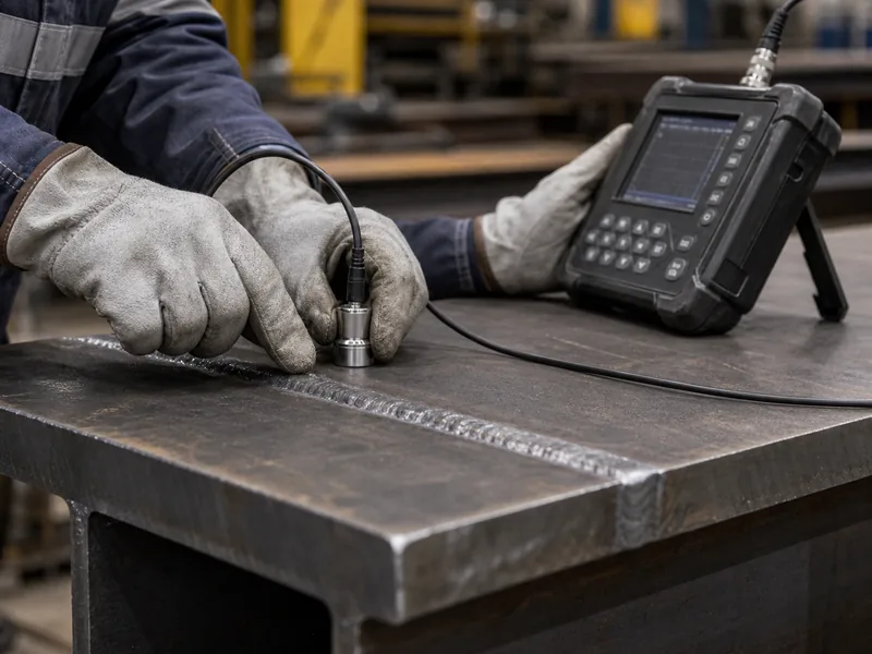
The defect that most concerns engineers is hydrogen-induced cracking, also called cold cracking. It can appear hours or even days after the weld cools, when three conditions combine: a hard, susceptible microstructure, dissolved hydrogen, and tensile residual stress. The defenses are preheating the steel to slow its cooling rate and using low-hydrogen consumables kept dry. Preheat for carbon steel commonly falls in the 200 to 400°F range, depending on thickness and carbon content. AWS D1.1 takes the late-cracking risk seriously enough to delay final inspection of certain quenched-and-tempered high-strength steels until at least 48 hours after welding.
Thicker or higher-carbon steel cools faster and raises the cracking risk, so the action is to apply preheat and hold the interpass temperature in range as the joint is built up. Other defects are more about technique: porosity from trapped gas when shielding is lost, undercut that grooves the base metal at the weld toe and cuts fatigue life, slag inclusions, and incomplete fusion. Each shows up in the inspection methods above, which is why the order is always weld, inspect, then load.
Welding vs Bolting in Steel Buildings
Welding and bolting are chosen by where the work happens and how the joint will be inspected, not by a simple ranking of one as better than the other. A welded joint is continuous and removes no cross-section, performs well under cyclic, dynamic, and seismic loads, looks smooth, and suits prefabrication. Its costs are skilled qualified welders, slower and weather-sensitive field work, more expensive inspection, and permanence. A bolted joint erects fast with simple tools, is unaffected by weather, can be removed or modified, and is easy to inspect, but its holes remove material and its preload may need checking over time.
| Factor | Welded | Bolted |
|---|---|---|
| Connection strength | Highest; full continuity, no holes | Reduced by bolt holes |
| Field speed | Slower, weather-sensitive | Fast, weather-independent |
| Cost in the field | Higher, skilled labor | Lower |
| Inspection | UT/RT, more involved | Visual and torque checks |
| Reversibility | Permanent | Removable, modifiable |
| Best for | Moment connections, dynamic loads, prefab | Erection, future changes |
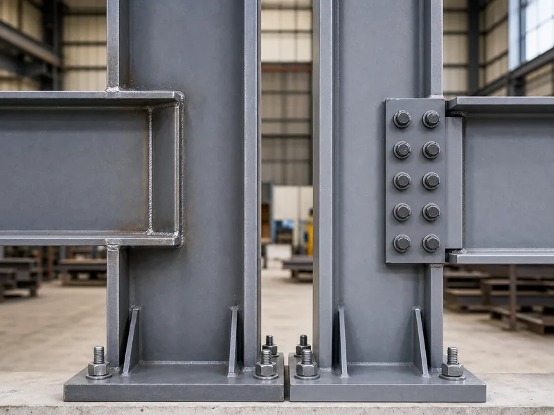
The industry answer is rarely one or the other. Built-up members and permanent connections such as column-to-base-plate and beam-to-column moment joints are shop-welded, while the field connections that hold the frame together during erection are high-strength bolted. The economics drive this split. Field welds tend to cost meaningfully more than the same welds made in the shop, and field welding is generally less productive, so fabricators concentrate welding under the shop roof and let bolts do the fast work on site. For a fuller look at that decision at the building level, see weld-up or bolt-up steel buildings.
Conclusion
On a steel building, sequence matters more than any single weld: settle the environment and load first, then the weld type, then the paperwork. Decide which connections are shop-welded and which are field-bolted, because that split follows directly from where the work happens and how the joint is loaded. Specify fillet welds for the routine connections and complete-joint-penetration groove welds where the joint must develop the member’s full strength. Then back the whole package with a qualified WPS, certified welders, preheat where the steel calls for it, and the inspection level the code demands for each weld. Get that sequence right and the individual welds disappear into a frame that behaves as one structure under load.
FAQ
Is welding stronger than bolting for steel connections?
A correctly designed weld can be as strong as or stronger than the member it joins, because it adds no bolt holes that remove cross-section. That continuity is why moment connections and members under dynamic or seismic load are often welded rather than bolted. Bolting can still be the better engineering choice when speed, reversibility, or field conditions matter more than peak joint strength.
What welding process is used for structural steel?
Stick welding (SMAW) and self-shielded flux-cored welding (FCAW-S) dominate field work because they tolerate wind, while gas-shielded flux-cored (FCAW-G), MIG (GMAW), and submerged arc welding (SAW) are used in the shop. The deciding factor is usually shielding: outdoors, a process that makes its own shielding survives the wind, whereas indoor work can use higher-deposition gas-shielded and automated processes.
What code governs structural steel welding?
AWS D1.1, the Structural Welding Code for steel, governs the design, qualification, fabrication, and inspection of welded structural steel in the United States. Connection design also relies on AISC 360, Chapter J. Together they decide how welds are sized, how procedures and welders are qualified, and how finished welds are accepted.
How are structural welds inspected?
All structural welds are visually inspected, and critical groove welds usually receive ultrasonic testing to find internal flaws. Radiographic, magnetic particle, and liquid penetrant testing cover other cases, from buried discontinuities to fine surface cracks. The method is matched to the weld type and its importance, and inspection happens before the structure is loaded.
Why do welders preheat structural steel?
Preheating slows the cooling rate so the weld zone does not form the hard, brittle microstructure that, combined with hydrogen and residual stress, causes cold cracking. It matters most on thick sections and higher-carbon steels, which cool fastest. Preheat is paired with low-hydrogen consumables and interpass temperature control as a single crack-prevention strategy.
Further Reading
- AWS D1.1, Structural Welding Code for Steel (American Welding Society) — the governing U.S. code for welding load-bearing steel, supporting the qualification and inspection requirements described above.
- Welding in structural steelwork (SteelConstruction.info, SCI/BCSA) — industry technical guidance on welding processes, weld types, welder qualification, and defect prevention in fabrication.
- Welding, Cutting, and Brazing (OSHA) — U.S. workplace safety standards for the hazards of welding operations on steel.