




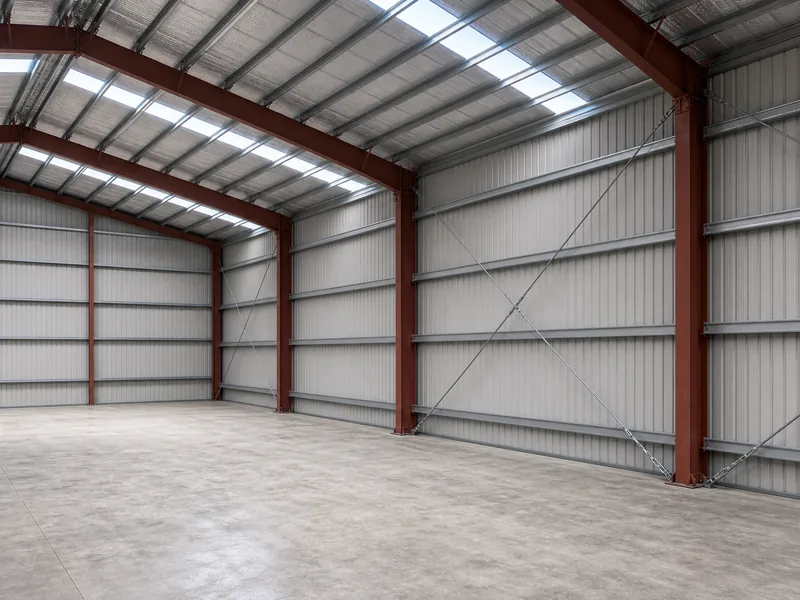
Steel frame bracing keeps a building from racking sideways or collapsing under wind and seismic loads by carrying those horizontal forces down through the frame to the foundation. The job is split across a few distinct systems — cross (X) bracing made from rods, cables, or angles; rigid portal frames; and wind columns — supported by secondary members such as flange braces and sag rods. Each one occupies a specific plane of the structure: the roof, the sidewalls, or the endwalls. Getting the right type into the right plane is most of what separates a frame that holds its shape for decades from one that drifts, cracks welds, or fails review. Bracing is a less visible part of steel frame construction, but it carries the loads that decide whether the structure survives a storm.
What Steel Frame Bracing Actually Does
Bracing gives a steel frame a defined path for horizontal load, so wind pressure and seismic shaking travel through dedicated members instead of bending columns and connections sized mainly for vertical weight. Three jobs sit behind that: controlling how far the frame leans, known as lateral drift; restraining slender members from buckling; and completing the load path down to the foundation. A bare rectangle of columns and rafters is strong straight down but weak sideways — push on one corner and the frame leans, or racks, like a parallelogram.
There are two ways to stop that. Rigid, or moment, frames make the joints stiff enough that the beams and columns resist the sideways push by bending. Braced frames keep the joints simple — nominally pinned — and add diagonal members that triangulate the bay; the diagonals take the lateral load in tension or compression while the columns handle gravity. Most metal buildings use bracing because triangulated steel is cheaper to fabricate and simpler to analyze than a frame full of moment connections.
The loads that drive all of this are the wind and seismic forces set by the local code. They determine how much horizontal force each braced bay has to move, which in turn sets the rod diameter, the connection size, and how many bays need bracing at all.
The Main Types of Steel Frame Bracing
Three primary systems carry most of the lateral load in a steel building — cross bracing, portal frames, and wind columns — with knee braces adding local stiffness at the eave. They differ mainly in how much they interfere with doors, openings, and clear floor space. All of them are fabricated and shipped as part of the building’s metal building framing components, arriving with the columns, rafters, and purlins they bolt to.
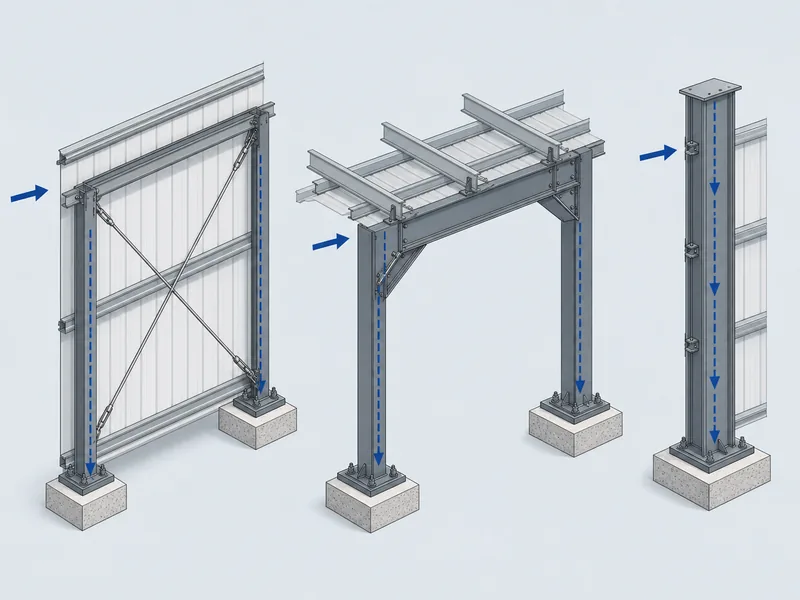
Cross (X) bracing — rods, cables, or angles
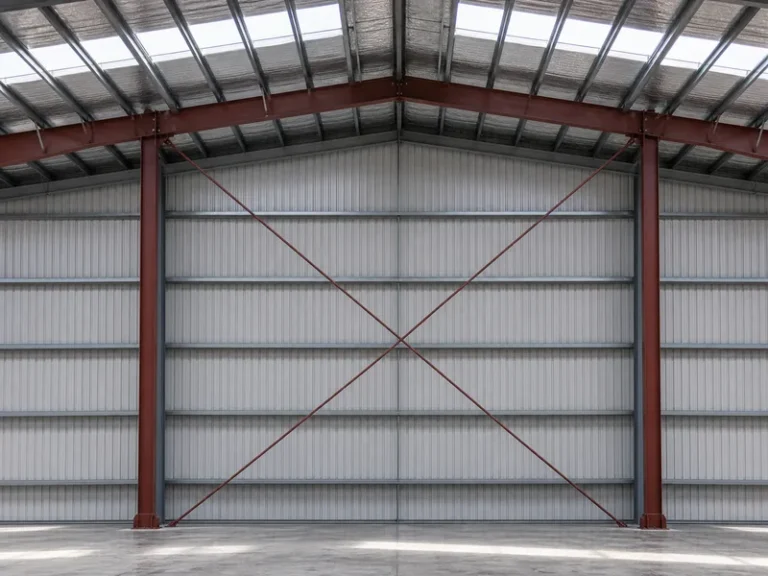
Cross bracing is the most common lateral system in pre-engineered metal buildings, formed by two diagonals that run corner to corner across a bay and meet in an X between two rigid frames. Under wind or seismic push, one diagonal goes into tension while the other slackens or takes compression, so the pair always keeps a tension member ready to drag the load down to the base.
The diagonals are usually steel rods, though angles and cables also appear. Rods carry more tension and stay taut, which is why they suit the heavier longitudinal lines; cables fit lighter loads, and angles step in when a member also has to handle some compression. Cross bracing lives in the sidewall and roof planes, and a single X is most efficient when its diagonals land closest to 45 degrees. Because the subject runs deeper than its role here, the full cross bracing picture — connection design and where the X can shift — gets its own treatment.
Portal frames — bracing around openings
Portal frames replace diagonal bracing with a rigid, moment-resisting assembly, which lets the lateral load path stay clear of a doorway or drive-through opening. Where an endwall or sidewall needs a wide door, an X-brace would cut straight across it; a portal frame — two columns tied to a beam with stiff connections — resists the sideways force by bending instead, leaving the opening usable.
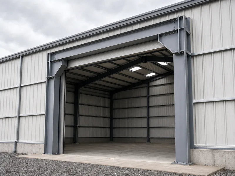
Portal frames cost more than a simple X and add fabrication at the connections, so they go only where openings or layout rule out diagonals. As a primary frame system, portal frames do more than brace, but in a braced building they earn their place at the large openings.
Wind columns and wind posts
Wind columns brace tall or wide endwalls by standing as vertical members that catch wind pressure across a large surface and deliver it to the frame above and the foundation below. A wind column ties to the main frame at the top and the slab at the bottom, splitting the wind reaction into a horizontal force at the eave and a moment at the base.
That base moment is why a wind column often needs a larger foundation pier than a braced bay — the pier has to resist rotation, not just downward load. Wind columns also carry limits: the local seismic category can restrict where they are allowed, so the choice is confirmed against the governing code rather than assumed.
Knee bracing — stiffening the column-to-rafter joint
Knee bracing adds a short diagonal between a column and the rafter at the eave, stiffening that corner without the full connection work of a moment frame. It is a middle ground — more rigidity than a simple pinned joint, less fabrication than a rigid portal. Knee braces often pair with flange braces at the haunch and suit smaller buildings or interior frames where a modest gain in stiffness is enough.
Flange Braces and Sag Rods: Secondary, Not Lateral
Flange braces and sag rods are stability members, not lateral-load bracing, and confusing the two is an easy way to under-build a frame. Flange braces — short angles, sometimes called purlin stays — connect the inner compression flange of a rafter or column to the adjacent purlin or girt. Their job is local: they stop that compression flange from buckling sideways under load, which lets the main member reach its rated capacity. They do not carry building sway to the foundation.
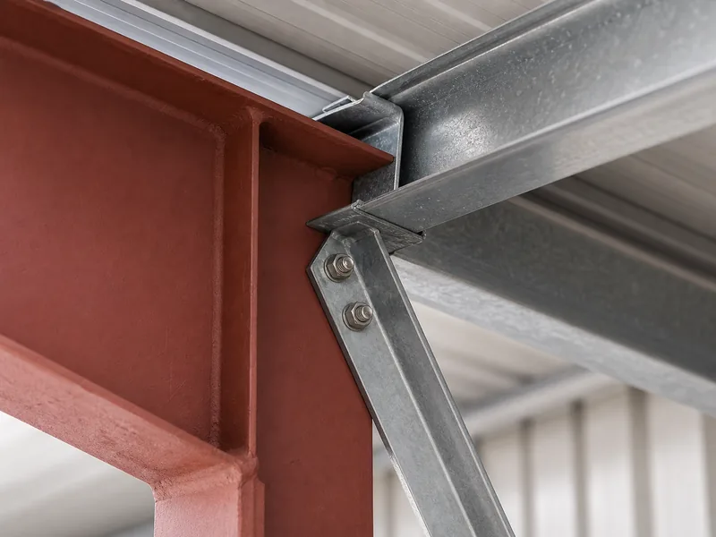
Sag rods are small-diameter rods threaded through the purlins and girts to limit deflection and hold alignment during erection — again, straightness and stability, not lateral resistance.
The distinction matters on site. A frame can have every flange brace and sag rod in place and still be unstable sideways if the X-bracing or portal frames were left out or relocated. Treating the secondary members as if they replace the primary system is how a building racks even though every brace appears installed.
How Bracing Carries Wind and Seismic Loads to the Foundation
A braced steel frame only works if the load has an unbroken path from the cladding to the footings, and bracing is what completes that path in the horizontal planes. Wind pushes on the wall and roof sheeting; the sheeting hands the pressure to the girts and purlins, which deliver it to the roof-plane bracing. The roof bracing passes it to the braced sidewall bays, the sidewall diagonals drag it down to the column bases, and the anchor bolts carry it into the foundation. Break any link — an omitted roof brace, a sidewall bay left open — and the load piles into members never sized for it.
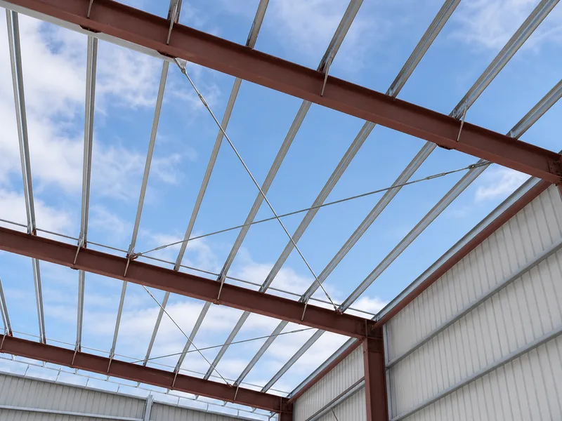
Roof-plane bracing usually forms an X connecting adjacent frames near the eave, and manufacturers cap how many bays sit between braced lines so the roof diaphragm does not get too flexible. The force these members carry is set by code. A standard engineering rule of thumb sizes stability bracing at roughly two percent of the force in the member it restrains, though the governing standard and the building’s wind and seismic demand decide the real number. Codes also limit how far a frame may lean out of plumb and when second-order sway effects must be checked. That is why brace sizing is verified by the engineer of record rather than estimated on site, and why the bracing layout and connection design follow the project loads, codes, and structural drawings.
One more system is temporary by design. During construction, before the permanent diagonals, flange braces, and sheeting are in place, temporary erection bracing holds the frame plumb and stable. Pulling it too early — before the permanent system can carry the load — is how frames go out of square, or worse, during erection.
Choosing and Placing Bracing in a Steel Building
Choosing a bracing layout is a trade between three variables: where the openings are, how strong the wind and seismic demand is, and how much foundation you are willing to build. The table below maps the three primary systems against those variables.
| System | Where it sits | Choose it when | Relative cost | Foundation impact |
|---|---|---|---|---|
| Cross (X) bracing | Sidewall and roof planes | Walls are mostly solid and the longitudinal lines are clear | Lowest | Standard column footings |
| Portal frame | Endwall or sidewall with a wide door | An opening blocks the diagonal line | Higher | Moderate; moment at the base |
| Wind column | Tall or wide endwalls | A large wall surface needs vertical support | Higher | Larger pier to resist rotation |
The pattern is simple: start with cross bracing, because it is the cheapest and lands on standard footings, then switch to a portal frame or wind column only where a door, a clear span, or the wall geometry blocks the diagonals. Seismic category can remove options — some configurations are restricted in higher categories — so the layout is checked against the local code before it is locked. All of this sits inside the wider steel building design process, where bracing is balanced against frame spacing, panel choice, and foundation cost rather than picked in isolation.
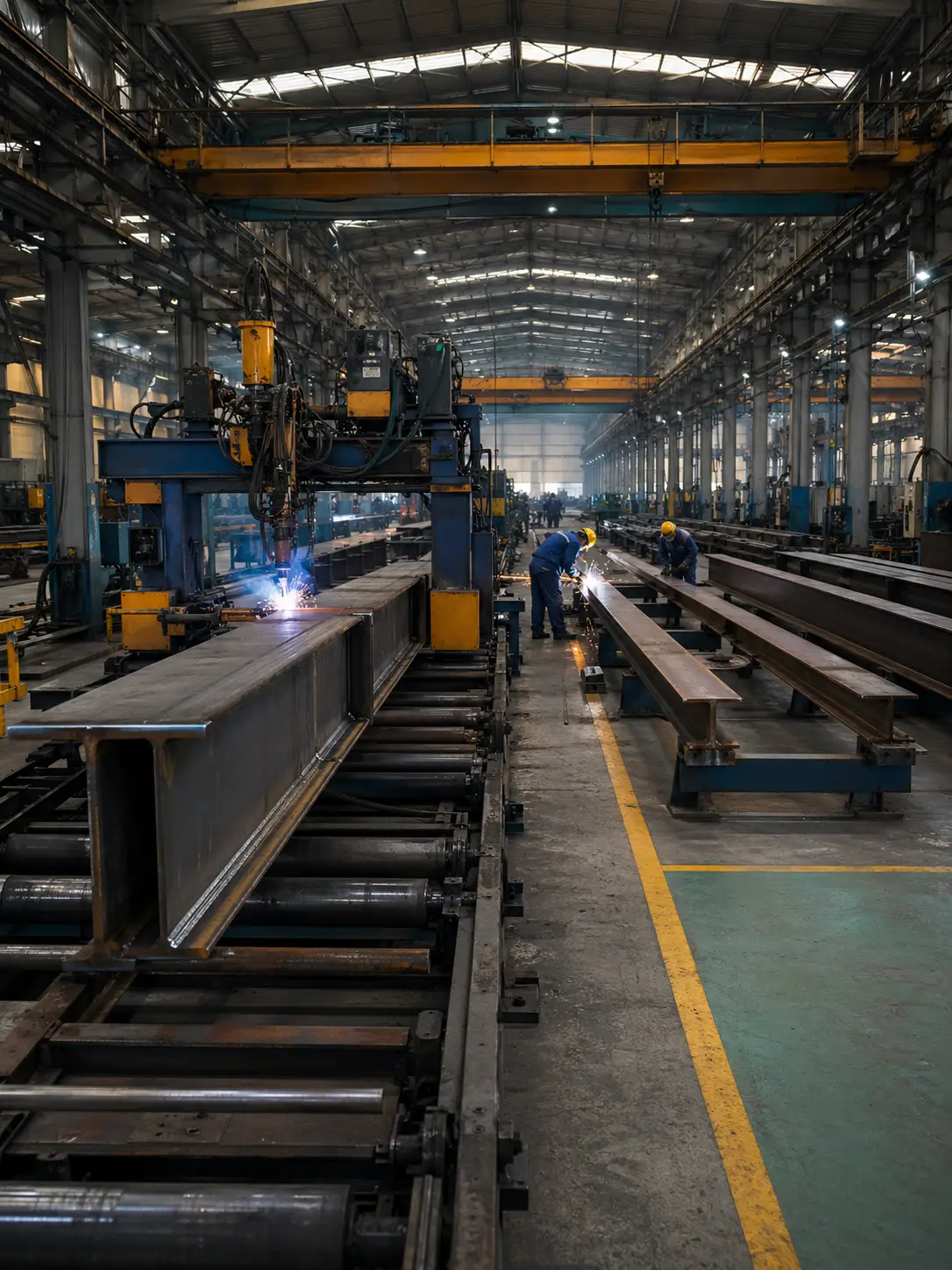
At KAFA, the bracing rods, angles, and flange braces are fabricated alongside the H-beam frames and C/Z purlins they connect to, produced under ISO 9001:2015 quality management at the company’s 20,000 m² Qingdao plant. One field caution outweighs the rest: bracing is not something to cut or relocate on site to make room for a door added late in the project. Moving a brace changes the load path and is an engineering decision, not a framing crew’s call. When a layout looks like it will fight the building’s intended use, it is cheaper to flag it before fabrication. The fix is to request a quote with the opening sizes and seismic category in hand, so the bracing can be designed around them from the start.
The order of decisions is what keeps a bracing layout sound: define the lateral system first, place cross bracing wherever the walls allow, and reserve portal frames and wind columns for the openings that genuinely need them. Flange braces and sag rods are then added as the stability layer they are, not as a substitute for that primary system. Once the wind and seismic demand, the door locations, and the seismic category are fixed, the bracing nearly designs itself — and any change to those inputs after fabrication is the moment to re-check the diagonals, not to work around them.
FAQ
Which steel frame bracing type should you expect by default?
Cross (X) bracing in steel rods is the standard lateral system in pre-engineered metal buildings, placed in the sidewall and roof planes. It wins out because rods are cheap, the X always keeps a diagonal in tension, and the load path down to the footings is short and direct.
Can you remove or relocate bracing to fit a door or window?
Relocating or removing a brace to fit an opening is an engineering change, not a field fix. Cutting an installed X-brace breaks the lateral load path; the correct move is a portal frame or wind column designed for that opening, which keeps the path intact while leaving the door clear.
What is the difference between a flange brace and cross bracing?
A flange brace and cross bracing solve different problems. The flange brace stops a compression flange from buckling locally so the rafter or column reaches its capacity, while cross bracing carries the whole building’s sideways load to the foundation — one is a stability member, the other a primary lateral system.
Do all steel buildings need bracing?
Every steel building needs a defined lateral system, whether that is diagonal bracing or moment frames. Even in low-wind regions, seismic forces and erection stability mean some lateral system is always engineered in; the only question is which type and how much.
Should you choose rod or cable bracing?
Steel rods suit heavier longitudinal lines because they carry more tension and stay taut, while cables fit lighter loads. Angles are the third option, used where a brace member also has to take some compression rather than tension alone.
Further Reading
- SteelConstruction.info – Braced frames — Steel Construction Institute / BCSA. Explains how braced frames differ from moment frames and how vertical and horizontal bracing planes share the lateral load.
- ASCE 7, Minimum Design Loads — American Society of Civil Engineers. The standard that sets the wind and seismic forces a building’s bracing has to resist.
- Metal Building Manufacturers Association — MBMA. Industry technical resources on metal building systems, including the wind and seismic design context behind pre-engineered framing and bracing.