A beverage manufacturing plant building is sized by product water treatment and the filling line, not by storage. The building houses water treatment, batching, filling, packing, and CIP rooms. Each room’s provisions follow the beverage format and its FDA rule: Part 129 for bottled water, Part 120 for juice, Part 113 for low-acid and Part 114 for acidified hermetically sealed drinks. Lock the water source and filling format first; both feed hall geometry and are costly to reverse once the shell is ordered.
What does a beverage manufacturing plant building house?
A beverage manufacturing plant building houses five process rooms whose provisions depend on the beverage format and the FDA rule that governs it. The plant layout follows one process order: source water enters treatment and becomes product water, meets syrup or concentrate in batching, then runs through blowing, filling, and capping before packing. A generic industrial shell can carry the frame, but each room asks the building for something specific. The table maps each room to the provision it drives and the variable to lock first.
| Process room | What the building must provide | Sizing variable to lock first |
|---|---|---|
| Water treatment | Impervious floor, drainage, chemical-resistant finish | Source water analysis and daily product-water demand |
| Syrup / batching | Hot-water supply, sugar handling, dust control | Batch volume and sugar form (bulk silo or bag) |
| Blow-fill-cap hall | Clear height, column-free span, air cleanliness | Container format and line speed in bottles per hour |
| Packing | Conveyor routing, pallet-load floor | Pack pattern and pallet throughput |
| Clean-in-place (CIP) / utilities | Chemical storage, ventilation, tank foundations | CIP circuit count and carbonation CO2 volume |
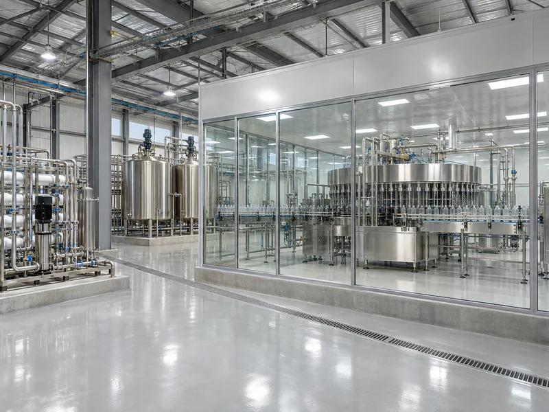
Most beverage plants are steel industrial buildings with a wet, chemically active interior, so the frame is the easy part. The room program is what separates a beverage plant from a dry warehouse. For the generic frame-and-cladding design flow, see steel building design; this guide stays on the beverage-specific provisions. Finished-goods beverage warehouse design is a separate scope outside this guide.
How does product water size the treatment room?
Product water is the ingredient that sets a beverage plant’s treatment room size, because every liter of finished drink draws a verified water-use ratio of source water. In most factories water is a utility; in a beverage manufacturing plant building it is the product itself, which reshapes the floor plan. The treatment train runs sand filtration, activated carbon, reverse osmosis, and polishing. It needs an impervious, drained room with chemical-resistant finishes, sized for the daily intake rather than the product volume alone.
The International Bottled Water Association’s 2024 benchmarking study reports a water-use ratio for North American bottled water plants. They use about 1.41 liters of water per liter of finished product, including the product water itself. For a plant producing 100,000 liters of bottled water a day, source water intake can be approximated as:
Daily intake ≈ 1.41 × daily product output = 1.41 × 100,000 ≈ 141,000 L/day (about 141 m³/day)
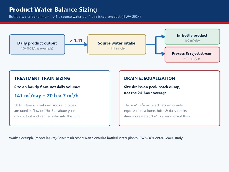
The remaining roughly 41 m³/day is process and reject water, which sets the drainage and wastewater load. This is a daily volume rather than a peak flow rate. Size the treatment train for the hourly flow your daily intake implies over the planned operating hours (141 m³/day over 20 h ≈ 7 m³/h), and size the drain and any equalization on peak simultaneous discharge. Plug your own daily output and a verified water-use ratio into the same expression. Juice and dairy drinks often draw more water than the bottled-water benchmark, so treat 1.41 as a bottled-water floor rather than a universal constant; verify your own ratio.
Why does the filling line set hall geometry?
The filling line format sets hall clear height, column spacing, and air cleanliness class in a beverage plant building. A PET blow-fill-cap monoblock is tall: the blower, filler carousel, and capper stack vertically, and overhead air conveyors route above them. A hall that clears a tall monoblock (around 6 m on large PET lines) plus overhead conveyor and maintenance access needs more clear height than a dry storage bay. A column-free span keeps the line route flexible, and clear span buildings suit this hall because the filling route cannot dodge columns. Hall length follows the line: the monoblock footprint plus upstream and downstream accumulation conveyors sets the clear span, so a faster line with longer accumulation needs a longer hall.
Air cleanliness is the second geometric driver: ISO 14644-1:2015 classifies air cleanliness by airborne particle concentration, from ISO Class 1 to 9. The class you need follows the product rather than the building. Aseptic filling of low-acid drinks needs a high-class local zone around the filler, while carbonated and acid drinks resist microbial growth and tolerate a lower clean-fill class. The class sets HVAC filtration stages, air-change rate, and room pressure cascade, so designers develop the filling hall’s envelope and air handling together. The older 100,000 / 1,000 class labels in some water-plant guides map loosely to ISO 8 / ISO 6. Specify the ISO class and the product sterility requirement instead of the legacy label.
Which FDA rules govern a beverage plant building?
The FDA rule that governs a beverage plant building depends on the product: bottled water, juice, and low-acid or acidified hermetically sealed drinks each fall under a different part. The baseline for every human-food facility is 21 CFR Part 117, the FSMA current good manufacturing practice and preventive-controls rule. It drives the building’s drainage, pest exclusion, airflow, and cleanable surfaces, and product-specific parts add provisions on top.
Bottled drinking water follows 21 CFR Part 129, whose scope covers the facilities, methods, practices, and controls used in processing, bottling, holding, and shipping bottled water. The identity and quality standard sits in 21 CFR §165.110. Juice and juice used as an ingredient in beverages fall under the juice HACCP rule, 21 CFR Part 120, so the hazard analysis sets the sanitation zoning and critical-control-point layout. Low-acid foods in hermetically sealed containers fall under 21 CFR Part 113, and acidified foods under 21 CFR Part 114.
The scope boundaries matter for the building: Part 113 defines low-acid food as a finished equilibrium pH above 4.6 and water activity above 0.85, and excludes alcoholic beverages. Part 114 explicitly excludes carbonated beverages, and most carbonated soft drinks sit below pH 4.6. They are acid foods outside Parts 113 and 114 and answer to Part 117 instead. Do not design a carbonated-drink hall to a low-acid canned-food rule it does not fall under. Confirm the product’s pH, water activity, and container seal before fixing the zoning.
What do syrup, CO2, and utilities demand?
Syrup batching, carbonation, and compressed air each add a building provision that a generic industrial shell does not carry. The syrup room needs hot water for dissolving sugar, a sugar-handling route, and dust control. Sugar is a combustible dust: OSHA’s combustible dust overview lists sugar among the food dusts that can explode when suspended in air at the right concentration. It cites the 2008 Georgia sugar explosion that killed 14 workers. A bag-dump or sugar-silo area therefore needs dust collection and housekeeping to limit settled dust, and its electrical classification must match the dust zone.
Carbonation adds bulk CO2 storage, usually an external tank, plus ventilation and monitoring in the filling hall. Carbon dioxide is about 1.5 times denser than air (molar mass 44 against roughly 29 g/mol for air), so a leak pools at floor level and in pits. OSHA’s annotated Table Z-1 sets a permissible exposure limit of 5,000 ppm as an 8-hour time-weighted average. The hall needs low-level extraction and CO2 monitoring at both floor level and breathing height. PET blowing adds high-pressure compressed air, and clean-in-place adds hot water, caustic, and acid storage with ventilated, drained rooms. These utilities are why a beverage plant’s mechanical scope runs well beyond a dry building’s.
How do liquid loads and corrosion shape the shell?
The slab, frame, and coating zoning of a beverage plant building follow liquid tank loads and sugar-acid splash. Treated-water and syrup tanks concentrate weight on a small footprint. A 20 m³ treated-water tank holds about 20 tonnes of liquid (20 m³ × 1,000 kg/m³), and that weight lands as a concentrated load, not a uniform floor load. Syrup is denser, so verify its density before sizing. The concrete slab for steel building and the metal building foundation under each tank must take that point load plus the tank self-weight. They are designed separately from the forklift wheel loads and racking loads elsewhere in the hall.
The wet interior attacks the shell in two ways a dry warehouse never sees. Product-contact surfaces use 316L stainless steel, but the shell is carbon steel that needs protection. Sugar and acid product splash, combined with chlorinated washdown, corrodes wall bases and fasteners. The fix is coating zoning that matches the splash and wash chemistry, with coved, washable corners at the wall-to-floor junction. Verify coating resistance against the actual chemical, concentration, and contact time, because atmospheric corrosivity classes alone do not prove chemical resistance. Above the filler, humidity and cold product surfaces condense on the ceiling and overhead steel, and the drip falls onto open product. Ceiling slope, metal building insulation, and a clean-to-less-clean airflow cascade keep that condensation off the line. For washable interior surfaces, see metal building interior wall finishing.
What belongs in the beverage plant building brief?
A beverage manufacturing plant building brief locks the water source and filling format before the shell is ordered, as both feed hall geometry. Confirm the source-water analysis and daily product-water demand first, and the container format and line speed second. The first sizes the treatment room and intake; the second sizes the hall height, span, and cleanliness class. Both are costly to reverse after fabrication, while syrup and CO2 utility details and the coating zoning can converge later in detailed design. They fit within the shell the first two variables set.
A bottled-water-only plant with no carbonation or aseptic filling can run in a standard industrial shell with a local water-treatment room. The beverage-specific zoning and gas utilities earn their cost only when you add carbonation, aseptic filling, or multiple container formats. We size the frame and slab around the tank loads and hall geometry you fix here, and we check the coating zoning against your wash chemistry before fabrication. Bring these beverage plant inputs to a scoping conversation:
- Product and format: beverage type, container (PET, can, glass, carton), and carbonation or aseptic requirement.
- Line speed: rated bottles per hour and the effective throughput after changeovers and CIP.
- Water source and demand: full source-water analysis and daily product-water volume, with a verified water-use ratio.
- Filling hall geometry: monoblock height, conveyor route, and the ISO 14644-1 cleanliness class for the product.
- Tank schedule: treated-water and syrup tank volumes, densities, and footprints for slab and foundation design.
- Sugar and gas utilities: sugar form (silo or bag), batch volume, bulk CO2 volume, and compressed-air pressure.
- Wash chemistry: CIP chemicals, concentrations, and temperatures for coating and drainage zoning.
- Applicable FDA part: the product’s pH, water activity, and container seal, so the governing rule is fixed.
- Site and cold chain: site constraints, and whether finished goods need a separate refrigerated warehouse design or a dry warehouse building design.
Four terms get used loosely in beverage plant briefs, and each changes a building decision once pinned to a measurable spec:
| Term | What it gets confused with | Normalize to |
|---|---|---|
| Capacity (BPH) | Effective throughput | Derate for changeovers and CIP before sizing the hall |
| Clean room | Aseptic filling | An ISO 14644-1 class plus a product sterility requirement |
| Water | Product water vs utility water | A treated-water ingredient spec separate from utility supply |
| Still vs carbonated | The same filling room | CO2 volumes, pressure rating, and low-level ventilation |
FAQ
What cleanroom class does beverage filling need?
The required class follows the product. Aseptic filling of low-acid drinks needs a high-class local zone, typically ISO 5 at the critical filler zone with an ISO 7 background. Carbonated and acid drinks tolerate a lower clean-fill class. Specify the ISO 14644-1 class and the sterility requirement together, then design filtration and pressure cascade to it.
How much water does a beverage plant use?
Bottled water plants average about 1.41 liters of water per liter of product, per IBWA’s 2024 study. Juice and dairy drinks often draw more. Use your own verified ratio.
Is a beverage plant building just a warehouse with machines?
No. Water treatment, filling geometry, and clean zoning drive the building; storage is a separate scope. A dry warehouse shell lacks the drainage, tank foundations, and air handling a beverage line needs.
Does juice HACCP apply to a low-juice drink?
The rule covers the juice ingredient. Part 120 applies to juice sold as such or used as an ingredient, so the juice in a low-juice drink must be processed under juice HACCP. The finished diluted beverage falls under Part 117.
Can carbonation be added to an existing shell later?
Set points such as CO2 volume can change. But the tank foundation, low-level ventilation, and monitoring are physical decisions that are costly to retrofit. Lock the carbonation requirement before the shell is ordered.